SLUAAP7 January 2024 BQ76905 , BQ76907
4 Timing Information
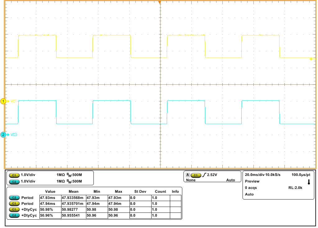
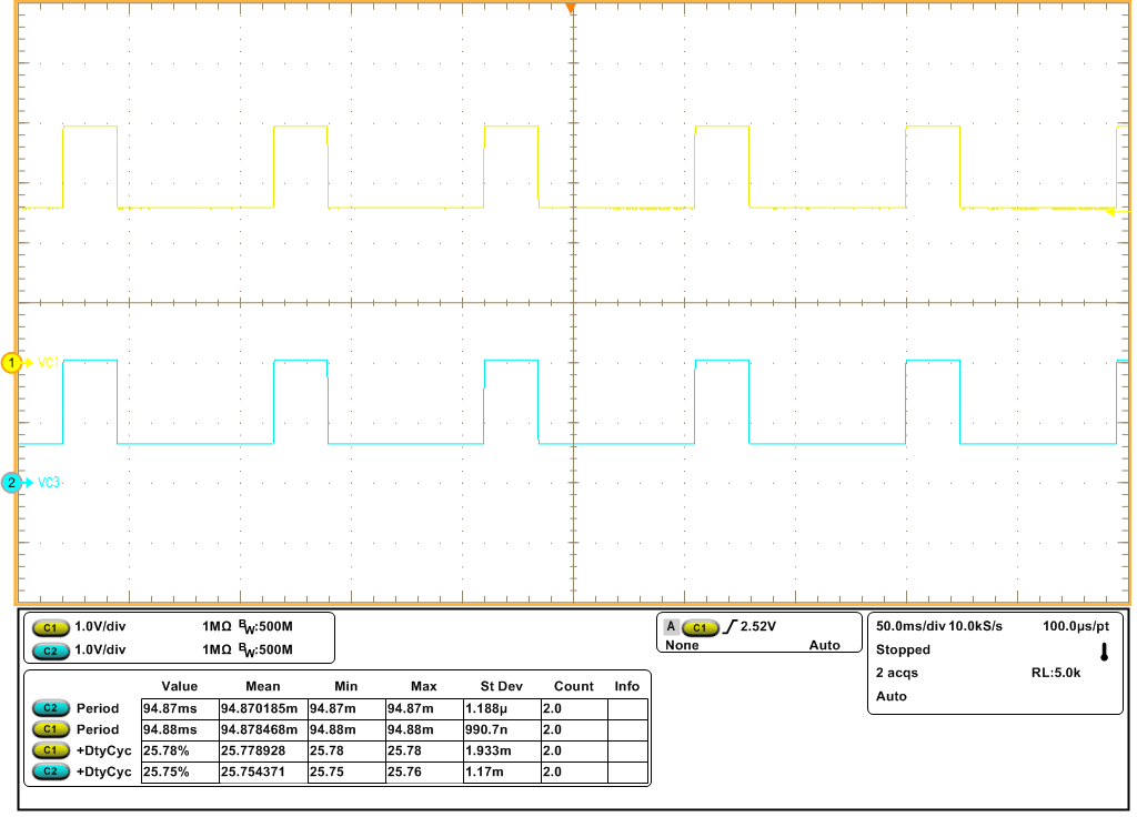
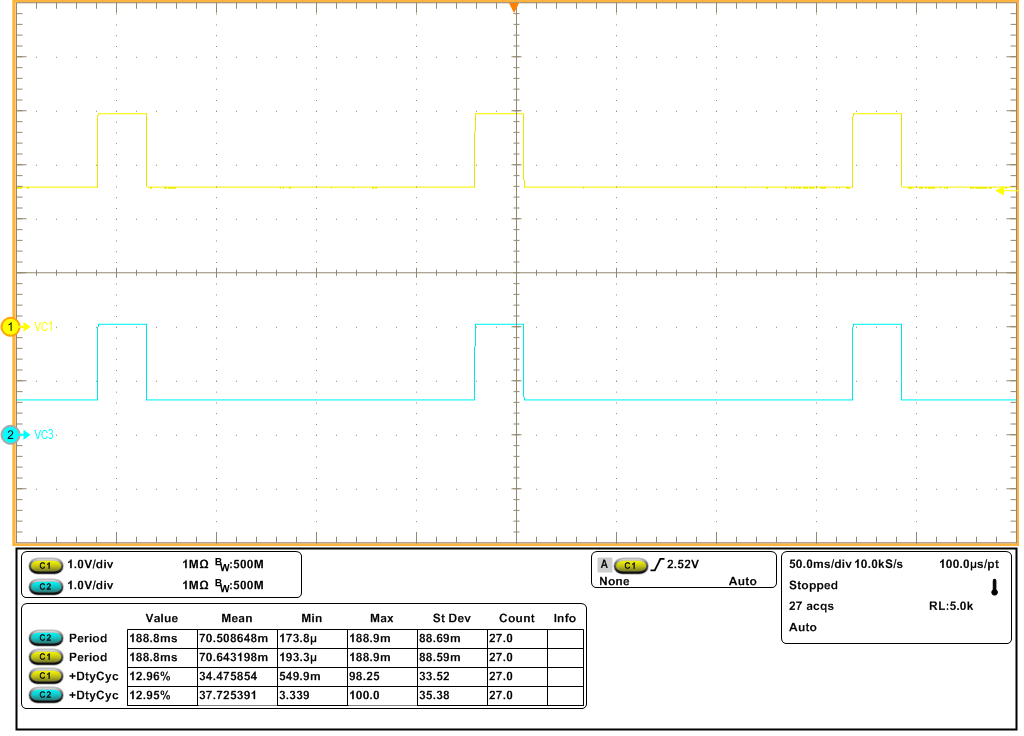
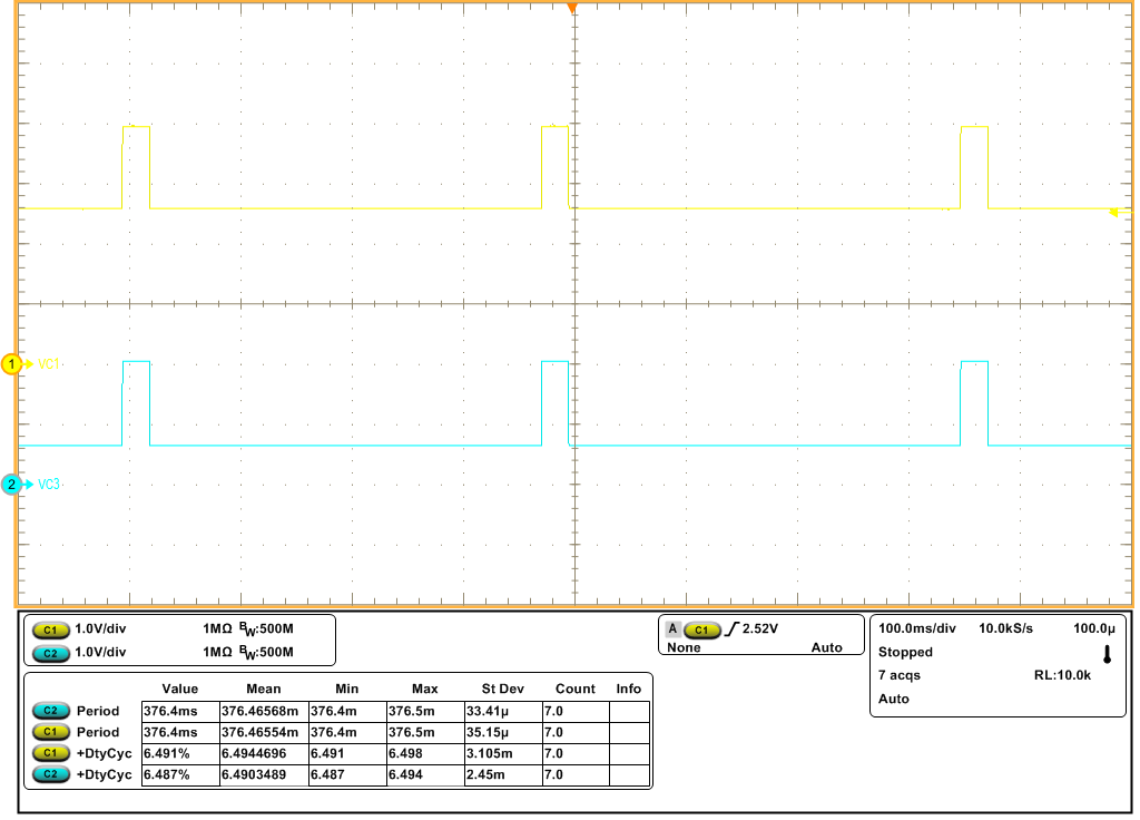
Due to the current that flows into the cell input pins on the BQ7690x while balancing is active, cell voltage measurements cannot be made without disabling balancing temporarily. Therefore, the timing for measurement of cell voltages and evaluation of cell voltage protections by the device is modified during balancing. While balancing of any cell is active, the balancing FETs are disabled temporarily during each ADSCAN while the cell voltages are being measured, as well as during the Shared Slot measurement. In order to meet the need for regular measurements while cell balancing is underway, the Settings:Configuration:Power Config[CB_LOOP_SLOW[1:0]] configuration bits modify the cell voltage measurement timing when cell balancing is active, to increase the average balancing current. This modification involves replacing the measurements in selected ADSCANs with idle slots of the same width, to allow balancing to remain active a higher percentage of the time.
| CB_LOOP_SLOW_1 | CB_LOOP_SLOW_0 | Description |
|---|---|---|
| 0 | 0 | Measurements are skipped in one of every two ADSCANs. |
| 0 | 1 | Measurements are skipped in three of every four ADSCANs. |
| 1 | 0 | Measurements are skipped in seven of every eight ADSCANs. |
| 1 | 1 | Measurements are skipped in 15 of every 16 ADSCANs. |
 Figure 4-1 Internal Cell Balancing With
CB_LOOP_SLOW = 0x00, Cell 1 (VC1) yellow, Cell 3 (VC3) blue
 Figure 4-2 Internal Cell Balancing With
CB_LOOP_SLOW = 0x01, Cell 1 (VC1) yellow, Cell 3 (VC3) blue
 Figure 4-3 Internal Cell Balancing With
CB_LOOP_SLOW = 0x10, Cell 1 (VC1) yellow, Cell 3 (VC3) blue
 Figure 4-4 Internal Cell Balancing With
CB_LOOP_SLOW = 0x11, Cell 1 (VC1) yellow, Cell 3 (VC3) blue
Figure 4-4 Internal Cell Balancing With
CB_LOOP_SLOW = 0x11, Cell 1 (VC1) yellow, Cell 3 (VC3) blueAt the time cell balancing is disabled (either indefinitely or periodically to allow regular cell voltage measurements), there will be a voltage transient generated that can affect several nearby cell input pins, due to the resistor and capacitor network at those pins. If a cell measurement occurs too quickly after cell balancing has been disabled, the accuracy of the cell voltage measurement can be impacted. In order to address this potential issue, the device includes a programmable delay implemented each time cell balancing is disabled before any cell voltage measurements are taken. This delay is set by Settings:Cell Balancing:Balancing Configuration[CBDLY2:0] from zero to 64 ms. It should be noted that this delay will increase the time between successive active measurement loops.
![Cell Balancing With
CB_LOOP_SLOW = 0x00 And Settings:Cell Balancing:Balancing
Configuration[CBDLY2:0] = 0x07 (64 ms delay), Cell 1 (VC1) yellow, Cell 3 (VC3)
blue GUID-20230503-SS0I-FRVC-QMD6-X5NH25PTFTZP-low.png](/ods/images/SLUAAP7/GUID-20230503-SS0I-FRVC-QMD6-X5NH25PTFTZP-low.png) Figure 4-5 Cell Balancing With
CB_LOOP_SLOW = 0x00 And Settings:Cell Balancing:Balancing
Configuration[CBDLY2:0] = 0x07 (64 ms delay), Cell 1 (VC1) yellow, Cell 3 (VC3)
blue
Figure 4-5 Cell Balancing With
CB_LOOP_SLOW = 0x00 And Settings:Cell Balancing:Balancing
Configuration[CBDLY2:0] = 0x07 (64 ms delay), Cell 1 (VC1) yellow, Cell 3 (VC3)
blue