SLUUCF8 March 2021 TPS53676
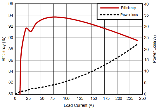
6.5 Efficiency Plot
RAILA is configured for 6-phases and refer to Table 4-2 for jumper setting (J10, J11, J12, J13)
- Make sure all default jumpers (J1 to J9) settings as shown in Table 4-3
- Connect three multimeters to measure input voltage, Input current, output voltage.
- Measure input voltage near power stage VIN pin capacitor (C96)
- Input current can be measured as voltage between TP14 and TP15 using RSENSE (0.5 mΩ)
- Measure output voltage on one of the top ceramic capacitor close to center phase (C221).
- Measure Output current from electronic load display.
Calculate efficiency from these 4 parameters ((Vout*Iout)/(Vin*Iin)).

| VIN = 12 V | VOUT = 880 mV | ||
| LOUT = 150 nH | DPS disabled | ||
| fSW = 500 kHz | RAILA, 6+1 |