SLUUD24 May 2024 BQ25770G
2.4 Equipment Setup
The test setup for BMS089 is shown in Figure 3-1. Please refer to the test setup and follow the guidelines below.
") Figure 2-1 Test Setup for BMS089 (BQ2577xGEVM)
Figure 2-1 Test Setup for BMS089 (BQ2577xGEVM)Use the following guidelines to set up the equipment:
- Set power supply #1 for 20V DC, 9A current limit and then turn off the supply.
- Connect the output of power supply #1 in series with a current meter to J1 (VIN and PGND).
- Connect a voltage meter across J1 (VIN) and J1 (PGND).
- Connect load #1 in series with a current meter to J2 (VSYS and PGND).
Connect a voltage meter across J2 (VSYS and PGND).
Set 2A at the constant current mode. Turn off load #1. - Connect Load #2 in series with a current meter to J3 (VBAT and PGND).
Connect a voltage meter across J3 (VBAT and PGND).
Set 15V at KEPCO load output. Turn off load #2.
Note: Add a 100µF capacitor on the BAT pin when testing without a real battery.
Connect J8 to the EV2400. Connect J8 to the SMBus PORT 1 (BQ25770G) or I2C PORT 2 (BQ25773G) on the EV2400. Figure 3-2 shows the connections.

The figure shows the SMBus version EVM connection. If the user is using the BQ25773GEVM, then move the connector to the I2C port.
Figure 2-2 EV2400 Connections- Install jumpers as indicated in Table 3-2.
- Turn on the computer and power supply #1. Open the bqStudio software.
- Select Charger and click the Next button.
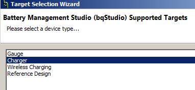
- For SMBus BQ25770G, select Charger_1_00_BQ25770_770G.bqz on the Select a Target Page. For I2C BQ25773G, select Charger_1_00_BQ25773_773G.bqz on the Select a Target Page.
- After selecting the target device, click the Read Register button and the interface in Figure 3-3 is presented. Device ACK OK appears on the top right corner of window to indicate a successful communication.
- Select Charger and click the Next button.
 Figure 2-3 Main Window of the BQ2577xG Evaluation Software