SLUUD36 July 2024 BQ25820
2.3.1 Equipment Set Up
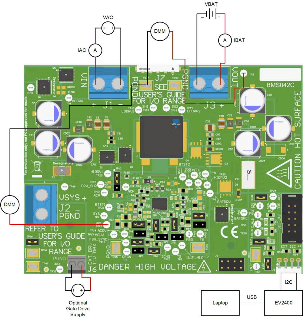
Use the following guidelines to set up the equipment:
- Set power supply 1 for 40V DC, 8A current limit and then turn off the supply.
- Connect the output of power supply 1 in series with a current meter to J1 (VIN and PGND).
- Connect a voltage meter across J1 (VIN) and J1 (PGND).
- Connect load 1 in series with a current meter to J3 (VBAT and PGND).
- Connect a voltage meter across J5 (VBAT and PGND).
- Set 23V at KEPCO load output. Limit KEPCO to 6A. Use load 2 to power EVM from the VOUT output.
- Connect J5 to the EV2400. Connect J5 to the I2C PORT 2 on the EV2400.
- Make sure the jumpers are installed as indicated in IO and Jumper Descriptions.
- Turn on the computer and load 2. Open the
bqStudio software.
- Select Charger and
click the Next button.
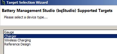
- Select Charger_1_00_BQ25820.bqz on the Select a Target Page.
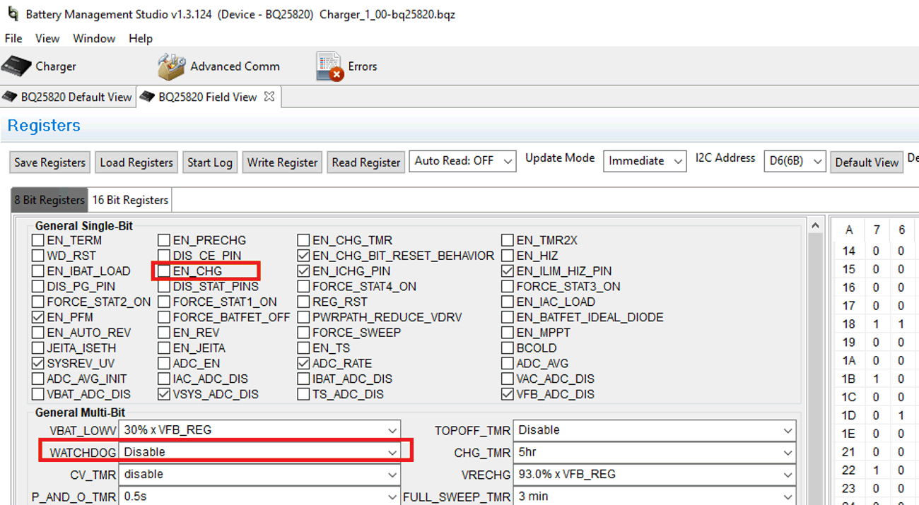
- After selecting the target device, click Field View. and then click the Read Register button.
- Select Charger and
click the Next button.
- Set WATCHDOG and EN_CHG
to disabled.
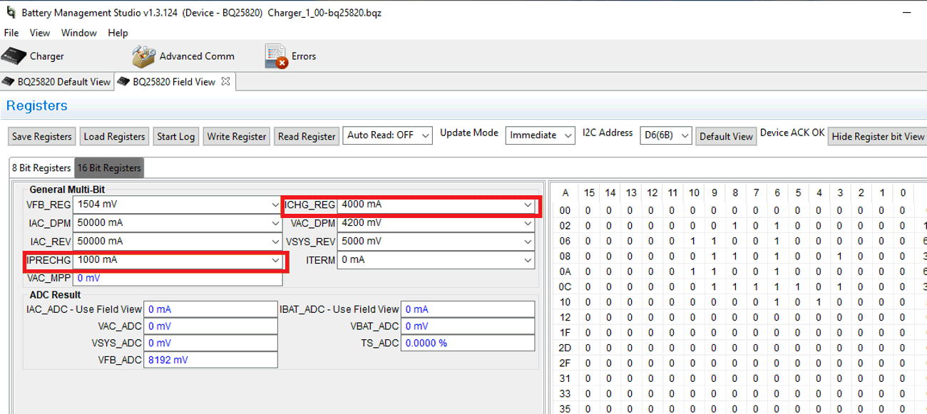
- In 16 Bit Registers, set ICHG_REG to 4000mA and IPRECHG to 1000mA.
- Turn on power supply #1, measure
V(J1(VAC)) = 40V ± 0.5V
I(J1(IAC)) = 2.4A ± 0.5A
V(J3(VBAT)) = 23V ± 0.5VI(J3(IBAT)) = 3.9A ± 0.5A
Use the following guidelines to test the BQ25820 EVM power path:
- Disconnect the power supply from J1 (VIN and PGND) and disconnect Load 1 from J3 (VOUT and PGND).
- Connect the output of power supply 1 to J3 (VOUT and PGND).
- Set power supply 1 for 20V DC, 8A current limit and then turn off power supply.
- Connect a voltage meter across J2 (VSYS) and J2 (PGND).
- Turn on power supply 1, measure V(J2(VSYS)) = 20V ± 0.5V.