SLUUD52 August   2024 TPS544E27


  1.   1
  2.   Description
  3.   Get Started
  4.   Features
  5.   Applications
  6.   6
  7. 1Evaluation Module Overview
    1. 1.1 Introduction
      1. 1.1.1 Before You Begin
    2. 1.2 Kit Contents
    3. 1.3 Specifications
    4. 1.4 Device Information
  8. 2Hardware
    1. 2.1 Test Equipment
      1. 2.1.1 Voltage Source
      2. 2.1.2 Oscilloscope
      3. 2.1.3 Multimeters
      4. 2.1.4 Output Load
      5. 2.1.5 Fan
      6. 2.1.6 USB-to-GPIO Interface Adapter:
      7. 2.1.7 Recommended Wire Gauge
    2. 2.2 List of Test Points, Jumpers, and Connectors
    3. 2.3 Efficiency Measurement Test Points
    4. 2.4 Control Loop Gain and Phase Measurement
    5. 2.5 External 5V Bias to Enhance Efficiency
    6. 2.6 Input Current Measurement
  9. 3Software
    1. 3.1 Opening the PMBus® Fusion GUI
    2. 3.2 Monitor Page
    3. 3.3 Status Page
  10. 4Implementation Results
    1. 4.1 Performance Data and Typical Characteristics Curves
  11. 5Hardware Design Files
    1. 5.1 Schematic
    2. 5.2 PCB Layout
    3. 5.3 Bill of Materials
  12. 6Additional Information
    1. 6.1 Trademarks

PCB Layout

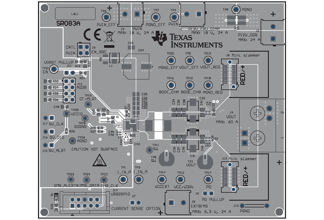
TPS544E27EVM TPS544E27EVM Top Composite ViewFigure 5-2 TPS544E27EVM Top Composite View
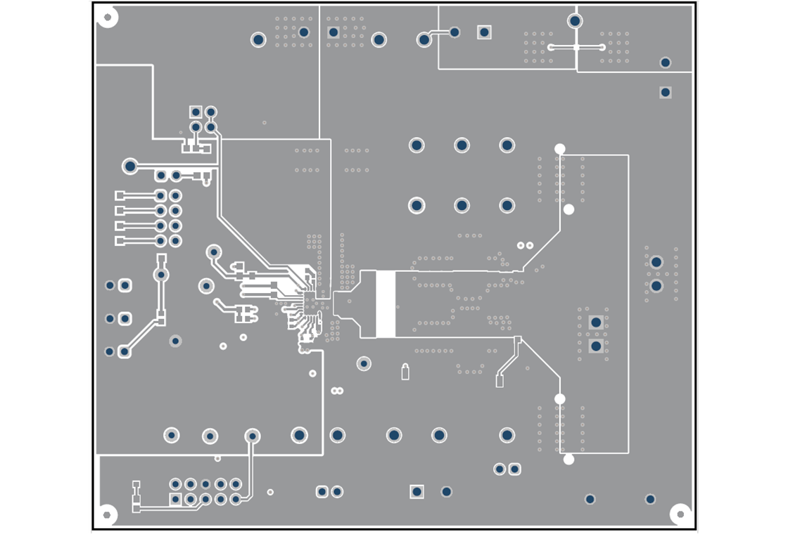
TPS544E27EVM TPS544E27EVM Top LayerFigure 5-4 TPS544E27EVM Top Layer
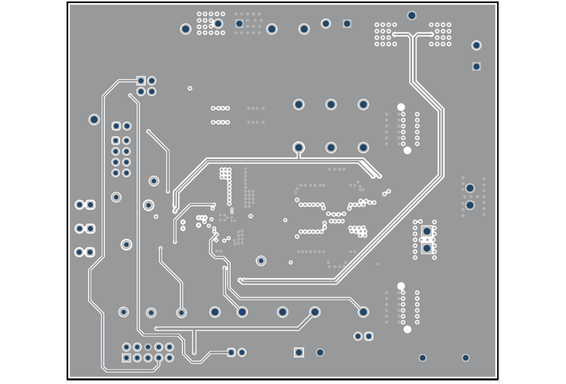
TPS544E27EVM TPS544E27EVM Layer 3Figure 5-6 TPS544E27EVM Layer 3
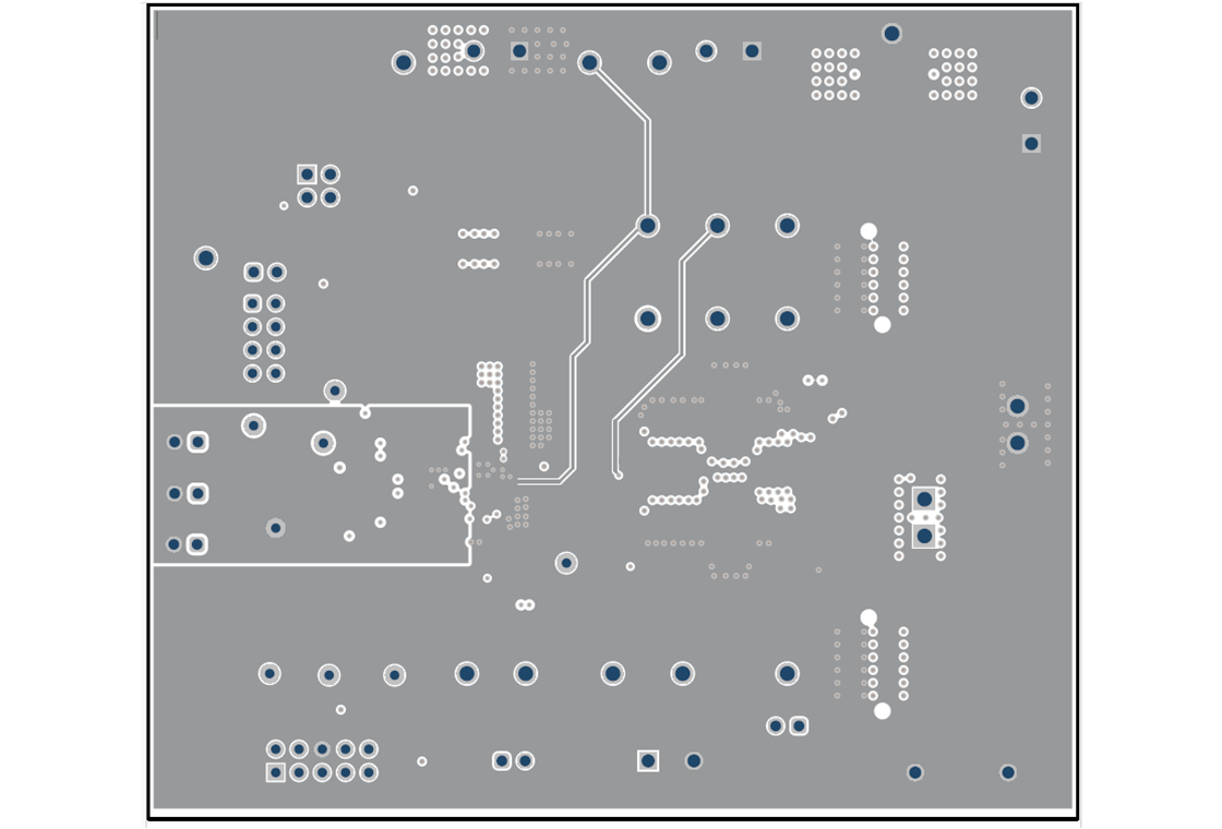
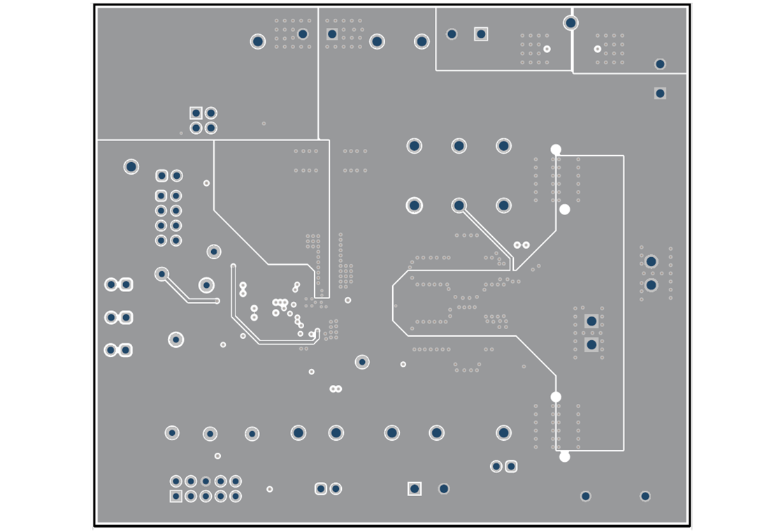
TPS544E27EVM TPS544E27EVM Layer 5Figure 5-8 TPS544E27EVM Layer 5
TPS544E27EVM TPS544E27EVM Bottom Composite View Figure 5-3 TPS544E27EVM Bottom Composite View
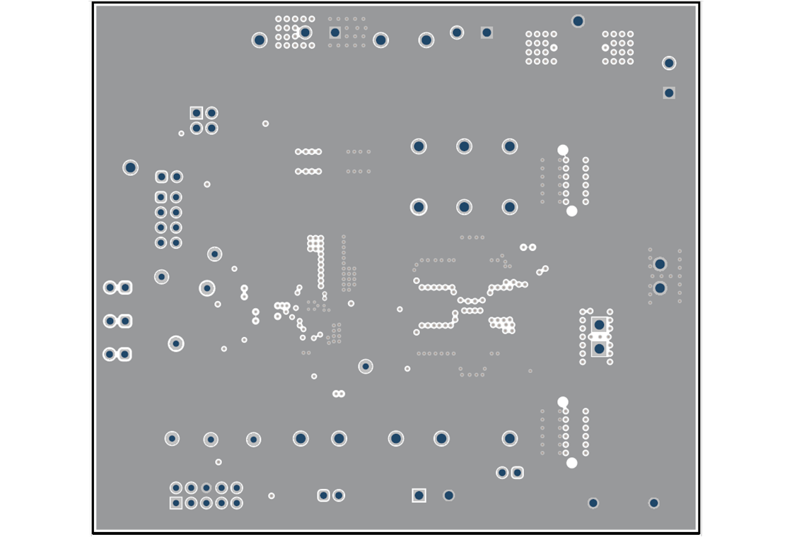
TPS544E27EVM TPS544E27EVM Layer 2Figure 5-5 TPS544E27EVM Layer 2
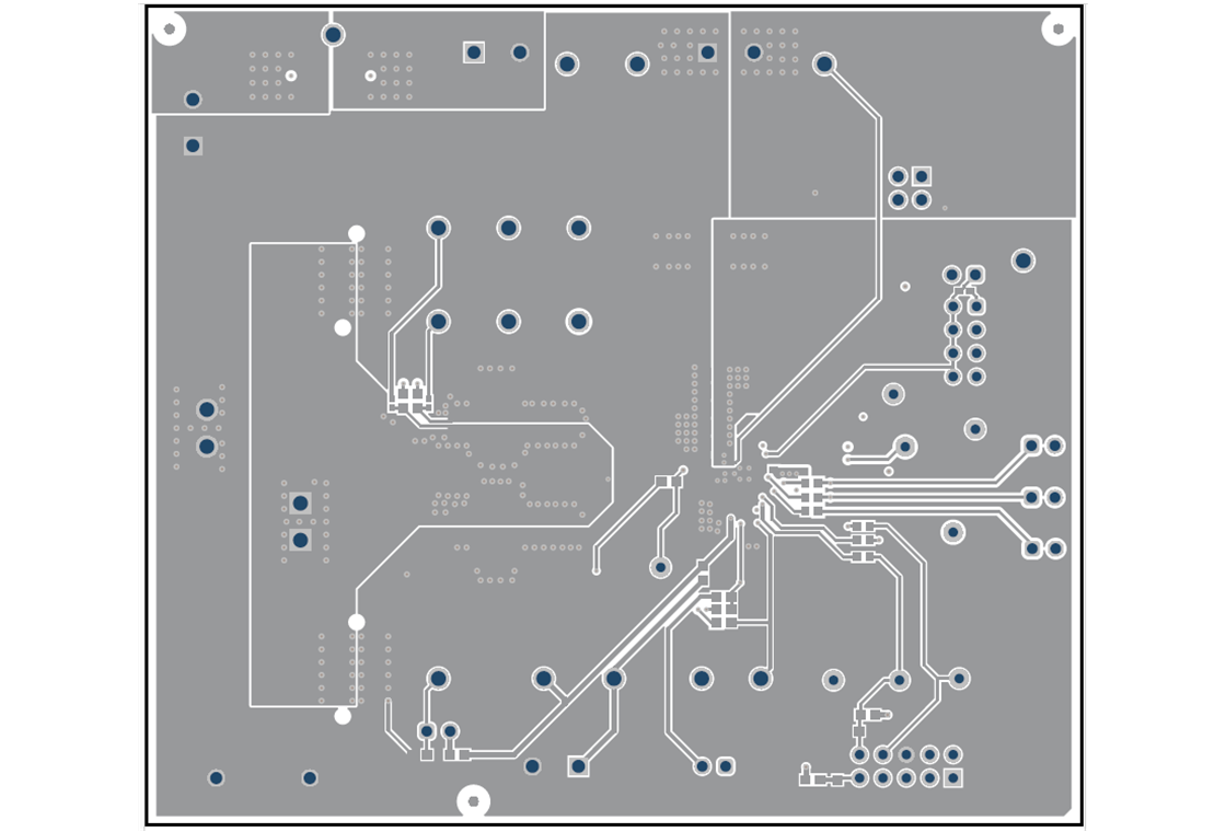
TPS544E27EVM TPS544E27EVM Layer 4Figure 5-7 TPS544E27EVM Layer 4
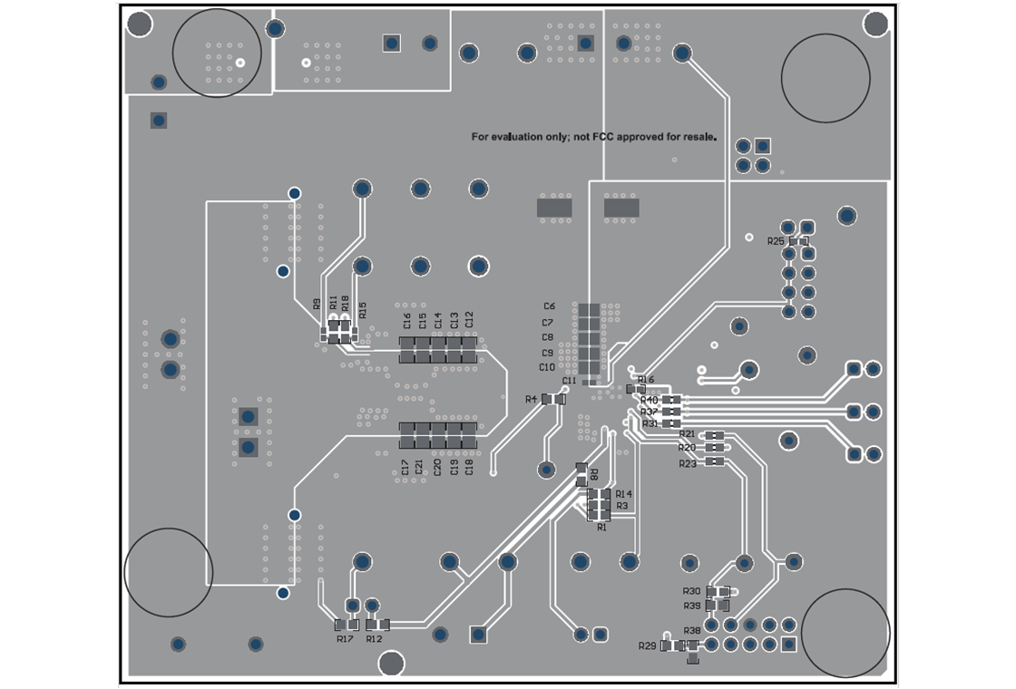
TPS544E27EVM TPS544E27EVM Bottom LayerFigure 5-9 TPS544E27EVM Bottom Layer