SLUUD60 October 2024 UCG28826
- 1
- Description
- Features
- Applications
- 1Evaluation Module Overview
- 2Hardware
-
3Implementation Results
- 3.1 Electrical Performance Specifications
- 3.2 Test Setup
- 3.3
Performance Data and Typical Characteristic Curves
- 3.3.1 Efficiency Result of 4-Point Average on 20VOUT
- 3.3.2 Efficiency Result of 4-Point Average at 15VOUT
- 3.3.3 Efficiency Result of 4-Point Average at 9VOUT
- 3.3.4 Efficiency Result of 4-Point Average at 5VOUT
- 3.3.5 Efficiency Typical Results
- 3.3.6 Output Characteristics
- 3.3.7 Key Switching Waveforms
- 3.3.8 Switching Frequency vs Load
- 3.3.9 Output Ripple Voltage
- 3.3.10 Load Transient Response
- 3.3.11 Line transient Response
- 3.3.12 Surge Test
- 3.3.13 Short Term Overload Operation
- 3.3.14 CCM operation
- 3.3.15 EN55022 Class B Conducted EMI Test Result
- 3.3.16 Thermal Images at Full Load (20 V and 3.25 A)
- 4Hardware Design Files
- 5Appendix - Efficiency
- 6Additional Information
3.3.15 EN55022 Class B Conducted EMI Test Result
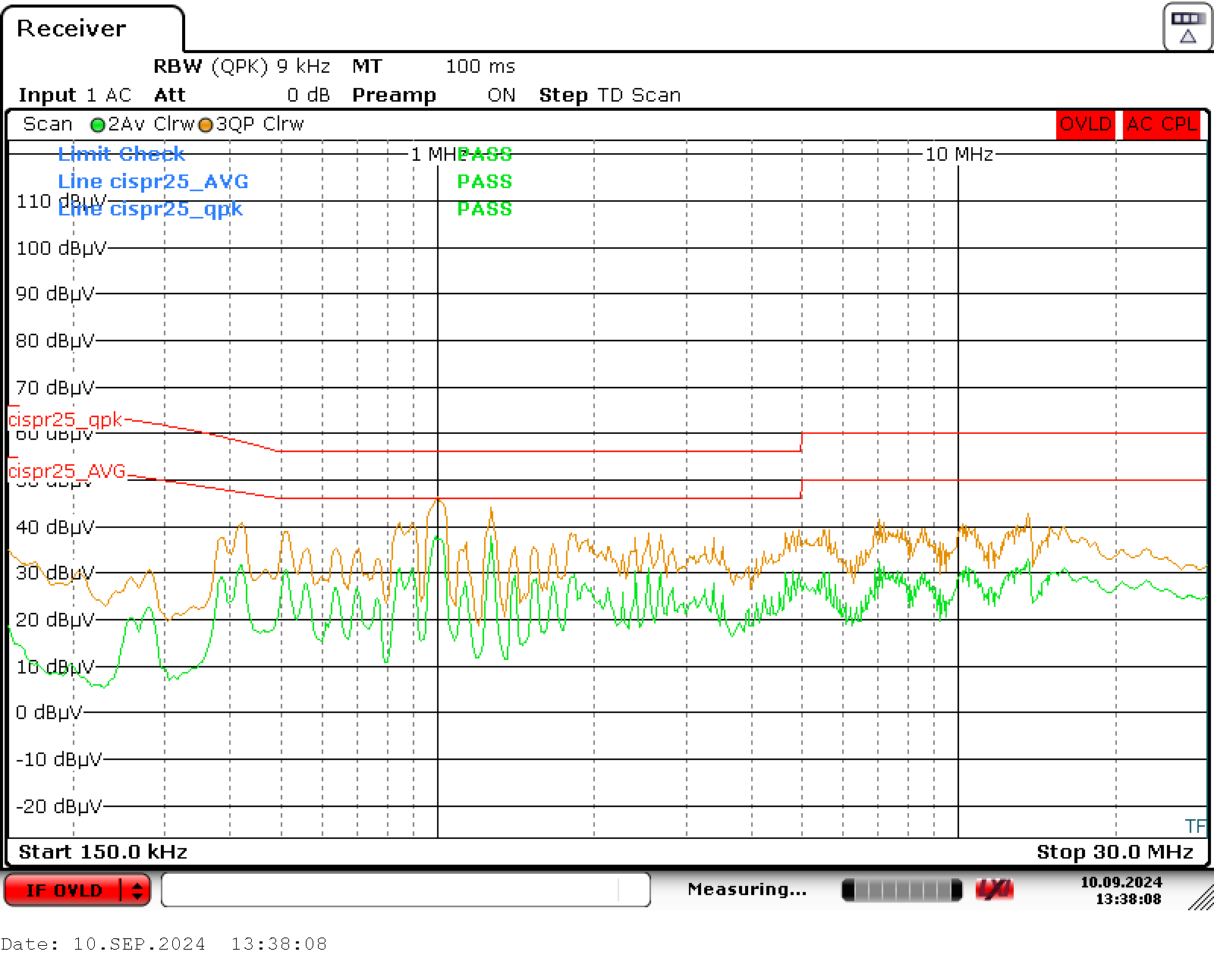
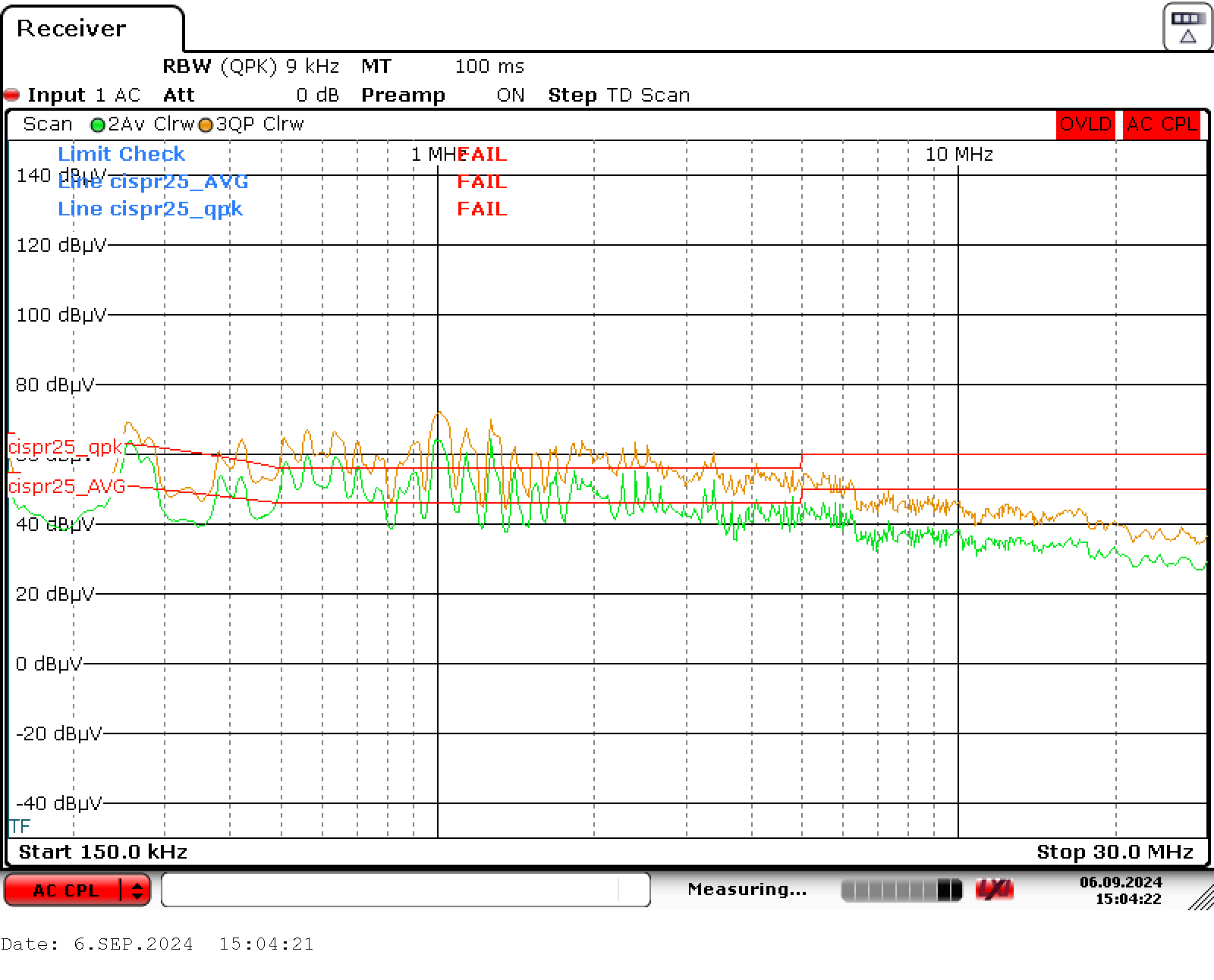
Please note this was evaluated on an EMI station for pre-qualification purpose only. TI recommends that all final designs be verified by an agency-qualified EMI test house. Figure 3-54 shows scan with existing EVM components. However, Figure 3-53 shows scan taken with the an additional DM choke of 22uH placed before L5 in the schematic. Final EMI analysis will be available in the final release of this EVM.
Please note this was evaluated on an EMI station for pre-qualification purpose only. TI recommends that all final designs be verified by an agency-qualified EMI test house. Figure 3-54 shows scan with existing EVM components. However, Figure 3-53 shows scan taken with the an additional DM choke of 22uH placed before L5 in the schematic. Final EMI analysis will be available in the final release of this EVM. Figure 3-53 VIN = 230VRMS, VOUT = 20V, Load = 3.25A (Output Not Grounded to LISN Ground) - With DM choke modification. Please note this was evaluated on an EMI station for pre-qualification purpose only. TI recommends that all final designs be verified by an agency-qualified EMI test house. Figure 3-54 shows scan with existing EVM components. However, Figure 3-53 shows scan taken with the an additional DM choke of 22uH placed before L5 in the schematic. Final EMI analysis will be available in the final release of this EVM.
 Figure 3-53 VIN = 230VRMS, VOUT = 20V, Load = 3.25A (Output Not Grounded to LISN Ground) - With DM choke modification. Please note this was evaluated on an EMI station for pre-qualification purpose only. TI recommends that all final designs be verified by an agency-qualified EMI test house. Figure 3-54 shows scan with existing EVM components. However, Figure 3-53 shows scan taken with the an additional DM choke of 22uH placed before L5 in the schematic. Final EMI analysis will be available in the final release of this EVM.
 Figure 3-54 VIN = 230VRMS, VOUT = 20V, Load = 3.25A (Output Not Grounded to LISN Ground) - Orginal EVM