SLUUD60A October 2024 – February 2025 UCG28826
- 1
- Description
- Features
- Applications
- 1Evaluation Module Overview
- 2Hardware
-
3Implementation Results
- 3.1 Electrical Performance Specifications
- 3.2 Test Setup
- 3.3
Performance Data and Typical Characteristic Curves
- 3.3.1 Efficiency Result of 4-Point Average on 20VOUT
- 3.3.2 Efficiency Result of 4-Point Average at 15VOUT
- 3.3.3 Efficiency Result of 4-Point Average at 9VOUT
- 3.3.4 Efficiency Result of 4-Point Average at 5VOUT
- 3.3.5 Efficiency Typical Results
- 3.3.6 Output Characteristics
- 3.3.7 Key Switching Waveforms
- 3.3.8 Switching Frequency vs Load
- 3.3.9 Output Ripple Voltage
- 3.3.10 Load Transient Response
- 3.3.11 Line transient Response
- 3.3.12 Surge Test
- 3.3.13 Short Term Overload Operation
- 3.3.14 CCM operation
- 3.3.15 EN55022 Class B Conducted EMI Test Result
- 3.3.16 Thermal Images at Full Load (20V and 3.25A)
- 4Hardware Design Files
- 5Appendix - Efficiency
- 6Additional Information
- 7Revision History
4.3.2 750847341Rev02 (WURTH)
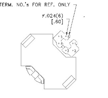
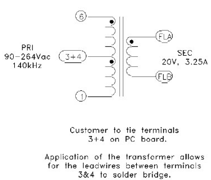
This 750847341Rev02 comes with a turns ratio of 7:1 and hence it is slightly less efficient than RLTI1464. The drawback of 750847341Rev02 is more leakage which slightly lowers efficiency. Interwinding capacitance is similar in performance to RLTI-1464 and also improves the thermal performance of UCG28826. The terminals 3 and 4 of the 750847341Rev02 needs to be shorted externally before these are inserted in to the EVM. There is another optimized variant from Wurth 750847341Rev03 which has a turns ratio of 6:1 with all other specifications remaining the same as the Rev02 variant. If using 750847341Rev02 variant, ensure C3 is 4.7nF capacitor like GRM21AR72H472KW10D, D3 is a slow diode like SL1K and R1 is close to 200kΩ like ERJ-P06J204V. R43 which is the turns ratio setting resistor needs to be changed to 25.5kΩ.
 Figure 4-6 750847341Rev02 pin
configuration
 Figure 4-7 750847341Rev02
schematic
| PARAMETER | VALUE | PINS/LEADS | TEST CONDITIONS |
|---|---|---|---|
| Inductance (µH) | 200μH ±10% | 6:1 | Open all other pins, 100kHz / 0.1Vac |
| Leakage Inductance (µH) | 6uH | 6:1 | tie(3+4,FLA+FLB),100kHz, 100mV, |
| D.C. resistance (Ω) | 0.23 | 6:1 | tie(3+4), @20ºC |
| D.C. resistance (Ω) | 0.03 | FLA:FLB | @20ºC |
| Dielectric (VAC, 60Hz) | 3000Vac | 1– FLA | tie(3+4), 3000VAC, 1 second , 1mA 60Hz |
| Turns-ratios |
7:1 |
(6-1):(FLA-FLB), tie(3+4) | APPLY: 1.0V @ 10kHz to (6 - 1) Vout: (FLA-FLB) 0.142V |