SLVAEF0 September 2020 – MONTH TPS92630-Q1 , TPS92638-Q1
3 Recommended Circuit For Device Enable Control
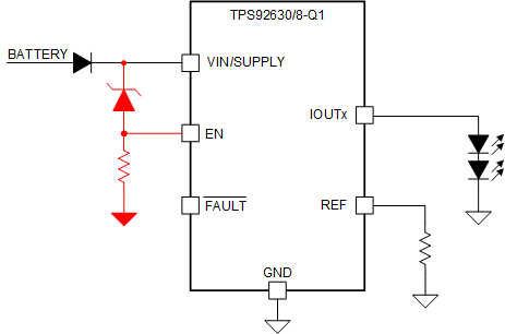
A recommended practical circuit to disable the device according to the power supply voltage is shown in Figure 3-1. A Zener diode is connected between V(supply) and EN and a resistor is connected from EN pin to ground to set a proper working current for the Zener diode.
 Figure 3-1 Recommended EN Control Circuit
The EN pin logic input threshold is shown in Table 3-1. Select a Zener diode with which you can ensure that the EN pin is lower than 0.7 V when V(supply) is lower than 5 V in order to shut down the device. And the device can be enabled when EN is higher than 2 V as V(supply) increases. For example, using a Zener diode with 4.7 V, 5% reverse voltage, the TPS92630/8-Q1 will be disabled when V(supply) drops to 5.165 V (MIN), and enabled when V(supply) is higher than 6.935 V (MAX).
| Parameter | MIN | TYP | MAX | UNIT | |
|---|---|---|---|---|---|
| VIL(EN) | Logic input, low level | 0 | 0.7 | V | |
| VIH(EN) | Logic input, high level | 2 | V | ||