SLVAEP4 October 2023 BQ79600-Q1 , BQ79612-Q1 , BQ79614-Q1 , BQ79616 , BQ79616-Q1 , BQ79652-Q1 , BQ79654-Q1 , BQ79656-Q1
7 Ring Architecture
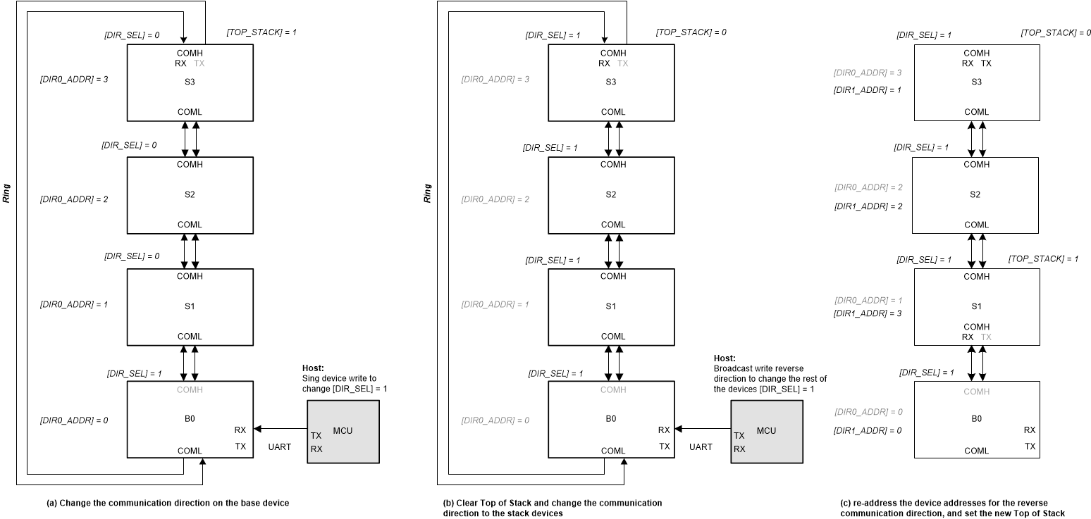
The bq7961X daisy chain interface offers the option to use ring architecture. In this architecture, a cable break between two devices does not prevent communication to all upstream devices as in a normal non-ring scheme. When the host detects a broken communication, the device allows the host to switch the communication direction to communicate with devices on both sides of the break. This allows for safe operation until the break in the lines is repaired. The CONTROL1[DIR_SEL] controls the communication direction. The devices will reconfigure the COMH and COML ports depending on the [DIR_SEL] and the [TOP_STACK] settings. Auto-addressing procedure is needed to re-address the device address for the reverse communication direction. Example to change the communication direction to [DIR_SEL] = 1 to the entire daisy chain:
- Host sends Single Device Write to change the base device [DIR_SEL] = 1. The base device will disable its COMH and enable its COML.
- Host sends Broadcast Write Reverse Direction to clear the COMM_CTRL register settings on all devices.
- Host sends Broadcast Write Reverse Direction to change the rest of the devices’ [DIR_SEL] = 1. In this step, the entire daisy chain set up to transmitting communication in the [DIR_SEL] = 1 direction (that is, each device set up to transmit command frames sent by host from its COMH to its COML).
- Host performs auto-addressing procedure to set up device address in the DIR1_ADDR register. Unless the devices have been reset, host can skip the dummy read/write steps to synchronize the DLL in the autoaddressing procedure.
- Host sets up the new Top of Stack device and the new ToS device will disable its COML transmitter.
Once the device address in both communication directions is set up, the host can skip auto-address step when switching communication direction.
 Figure 7-1 Example to Change Communication Direction in Daisy Chain
In a broken cable case, the host follows the same procedure to change the communication direction. To access all devices in the daisy chain, the host will have to communicate with [DIR_SEL] = 0 on some devices and communicate with [DIR_SEL] = 1 on other devices in the daisy chain. The chain will also have two ToS devices, one for each communication direction.
 Figure 7-2 Using Ring Architecture to Access All Devices in a Broken Cable Case