SLVAEX2 September 2020 – MONTH TPS55288 , TPS55288-Q1 , TPS552882 , TPS552882-Q1
3.1 Test Result
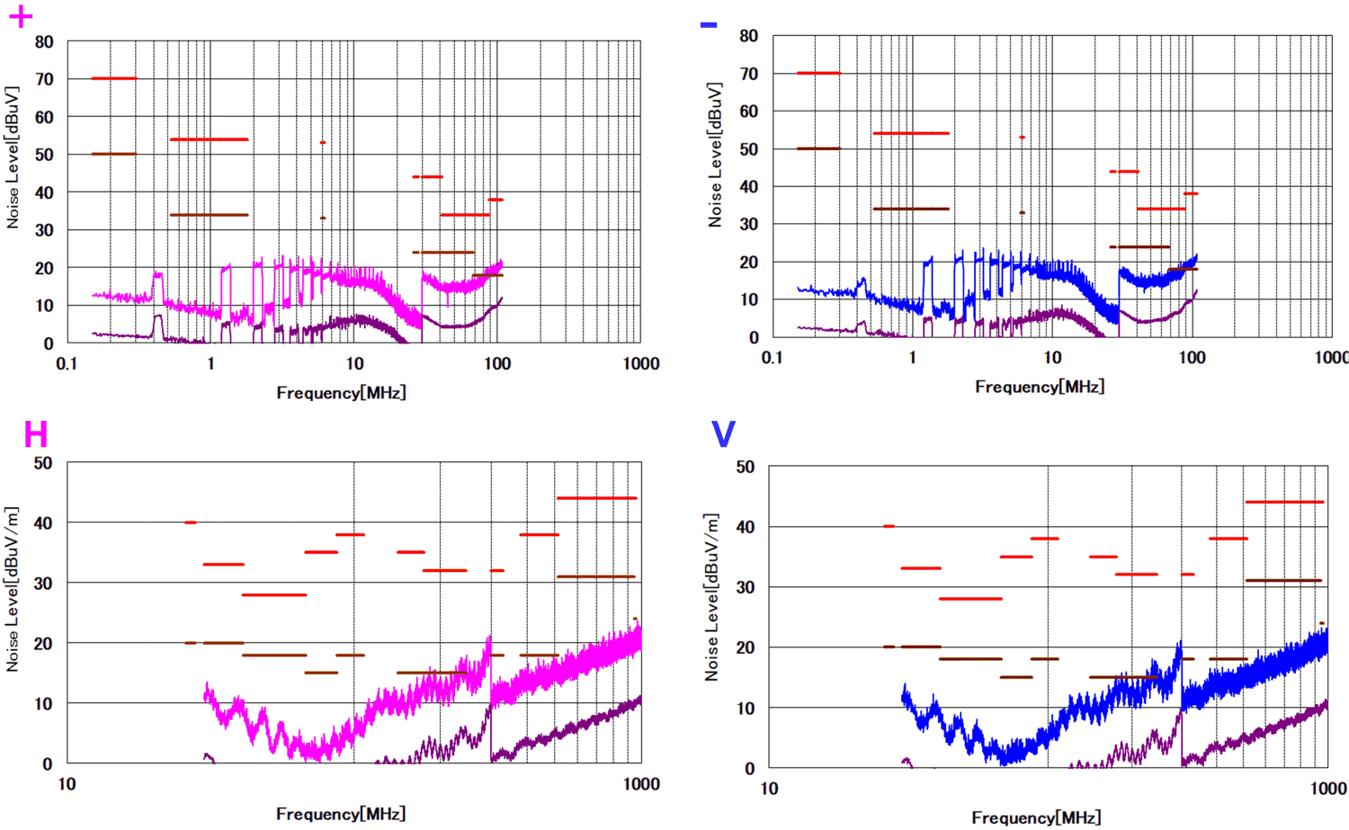
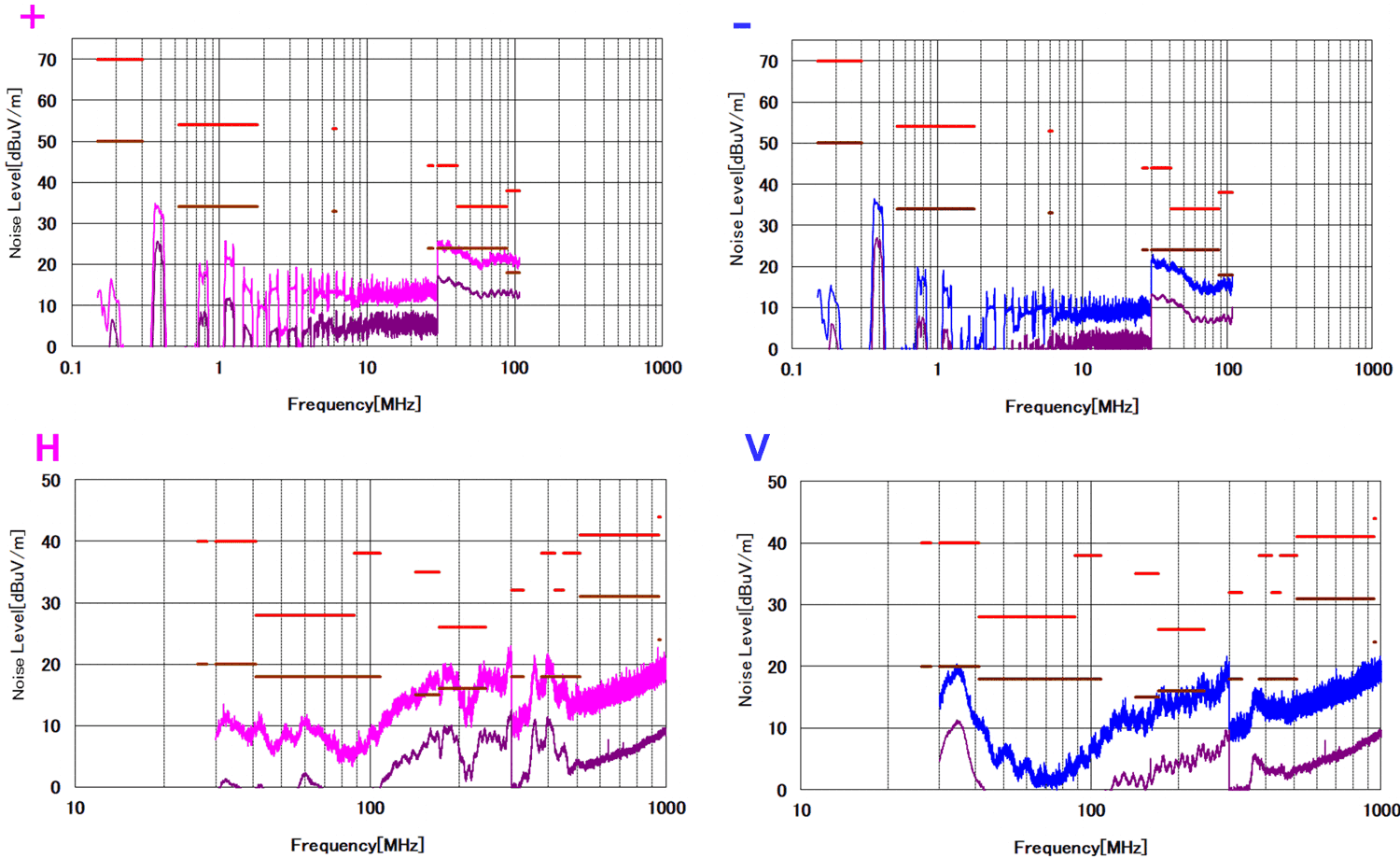
Figure 3-2 shows the EMI test result under buck mode. Figure 3-3 shows the EMI test result under boost mode. It is clearly illustrated that both the conduction EMI and the radiation EMI passed the CISPR25 level 5 limit with more than 6-dB margin.
 Figure 3-2 Buck Mode EMI Result (VIN = 12 V,
VOUT = 5V / IOUT = 3A)
 Figure 3-3 Boost Mode EMI Result (VIN = 12
V, VOUT = 20V / IOUT = 3A)