SLVAEZ0 November 2020 TPS1H000-Q1 , TPS1H100-Q1 , TPS1H200A-Q1 , TPS1HA08-Q1 , TPS1HB35-Q1 , TPS2H000-Q1 , TPS2H160-Q1 , TPS2HB16-Q1 , TPS2HB50-Q1 , TPS4H000-Q1 , TPS4H160-Q1
4 How to Leverage Thermal Simulations
The main benefit of having the simulation is to identify whether or not the HSS will enter thermal shutdown where it can shutoff or reduce the current that is being provided to off-board loads. Typically this is done when designing for an application where there is a significant amount of capacitance on the load.
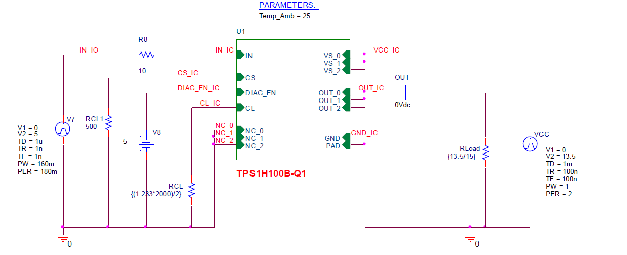
Figure 4-1 shows an example where the TPS1H100B-Q1 enters thermal shutdown as it is modeled in PSpice.
 Figure 4-1 Schematic
Setup for TPS1H100B-Q1 Simulation With 15- A
Load
Figure 4-1 Schematic
Setup for TPS1H100B-Q1 Simulation With 15- A
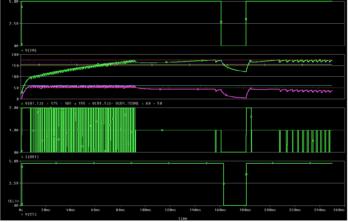
LoadFigure 4-2 illustrates the simulation results that show the thermal fault:
 Figure 4-2 Results
for TPS1H100B-Q1 Simulation With 15-A Load
Figure 4-2 Results
for TPS1H100B-Q1 Simulation With 15-A LoadThis shows that even though the device will limit the current to 2 A, the device will enter thermal shutdown as the load attempts to continuously pull the current to 15 A. The simulation also shows approximately how long it takes for the TPS1H100B to enter thermal swing shutdown in the purple waveform. Thermal swing shutdown occurs when the junction temperature and controller temperature within the device exceeds a temperature difference of 50°C, causing the device to shut down until the difference is below the threshold. The similar green waveform shows the junction temperature and when this waveform exceeds 175°C, the device reduces the output current limit to 1 A, a feature known as current limit fold-back that is used to cool the device. Once both of these temperature thresholds are no longer exceeded, the device outputs a current of 2 A temporarily before going back into thermal shutdown.
With the thermal modeling simulation from PSpice, the TPS1H100B device is shown to not handle the 15-A load even with a current limit and a different device should be used for this application.