SLVAFL1 October 2024 TPS25751 , TPS26750
2.1 Boot Process
At boot, the PD controller can first read the Header_ID from the Low Region at the address LowRegionStart and LowAppConfigOffset. If any error occurs in reading the Low Region Header_ID, the PD controller can then read the Header_ID from the High Region at the address HighRegionStart and HighAppConfigOffset. If any error occurs in reading the High Region Header_ID, the PD controller can loop back and try the Low Region again. The PD controller can only make two attempts, after that PD controller aborts the EEPROM loading process.
If the PD controller reads the correct Header_ID (PD controller is expecting 0xACE0_0001) in the Low Region, then it can begin reading the Patch Bundle from the Low Region. If there is a CRC error while reading the Patch Bundle, the PD controller does not attempt to read from the High Region. If the PD controller reads the correct Header_ID in the High Region, then it can begin reading the Patch Bundle from the High Region. If there is a CRC error while reading the Patch Bundle, the PD controller can attempt to read from the Low Region. However, the PD controller does not make more than two attempts on any region.
Therefore, when updating one of the regions of the EEPROM it is critical to verify the new Patch Bundle in the region before pointing the Region Start to it.
If the EEPROM loading process is aborted, then the PD controller can update the BOOT_STATUS register accordingly and assert the INT_EVENTx.ReadyForPatch interrupt. the PD controller then waits indefinitely for the host to load a patch over the I2Cc port or to issue a GAID 4CC command to reboot the PD controller. This behavior also occurs when there is no EEPROM present.
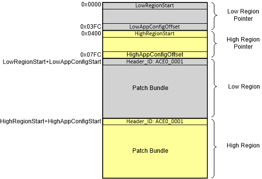
Figure 2-1 shows the memory map of the EEPROM and where the pointers and offsets reside assuming that the EEPROM has initially been written with the same Patch Bundle in both regions. The PD controller looks for the Header_ID of the Low Region at address LowRegionStart and LowAppConfigOffset, and it looks for the Header_ID of the High Region at the address HighRegionStart and HighAppConfigOffset.
 Figure 2-1 EEPROM Memory Map