SLVAFL1 October 2024 TPS25751 , TPS26750
2.4 EEPROM Update Example
In the following example, the assumption is that the initial state of the EEPROM is that the Low Region and the High Region both have the same Patch Bundle. The PD controller can boot from the Low Region. Figure 2-6 shows the EEPROM memory map for this initial condition.
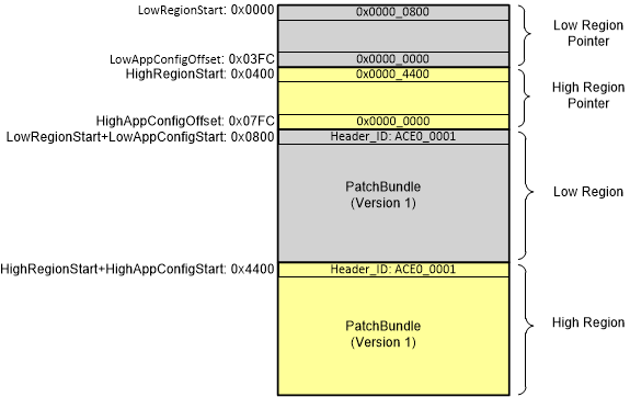 Figure 2-6 Initial State of the
EEPROM
Figure 2-6 Initial State of the
EEPROMWhen the host must update the Patch Bundle that the PD controller uses for booting, it first erases the High Region pointer so that if there is an interruption while writing the new Patch Bundle to the High Region, it is guaranteed the PD controller does not attempt to load it. Specifically, Step 1 of the function UpdateRegionOfEeprom(1) from Figure 2-3 is executed, and Figure 2-7 shows the memory map after the High Region pointer has been erased successfully. If booted in this state, Patch Bundle (Version 1) is loaded from Low Region.
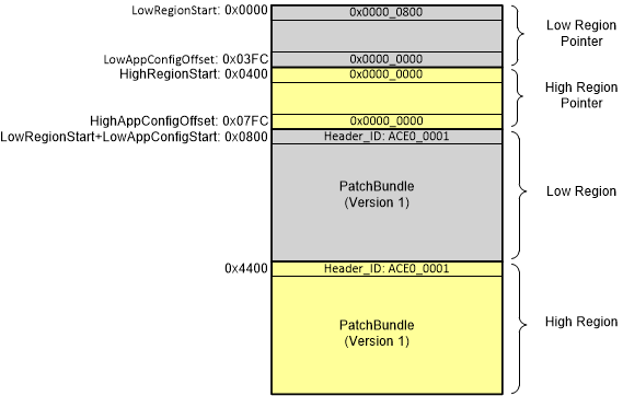 Figure 2-7 State of the EEPROM following
UpdateRegionOfEeprom(1) Step 1
Figure 2-7 State of the EEPROM following
UpdateRegionOfEeprom(1) Step 1Next, the host writes the new Patch Bundle (Version 2) to the High Region. Specifically, Step 2 of the function UpdateRegionOfEeprom(1) from Figure 2-3 is executed, and Figure 2-8 shows the memory map following this step. Note that if the PD controller boots with the EEPROM in this state, the controller does still load Patch Bundle (Version 1) from the Low Region.
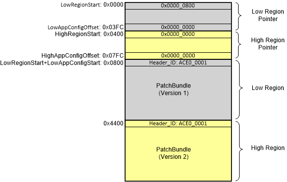 Figure 2-8 State of the EEPROM following
UpdateRegionOfEeprom(1) Step 2
Figure 2-8 State of the EEPROM following
UpdateRegionOfEeprom(1) Step 2Next, the host can verify the contents of the EEPROM High Region using the FLvy command. If that succeeds, then the host can write 0x4400 into HighRegionStart at address 0x0400. This happens in Step 3 of UpdateRegionOfEeprom(1) in Figure 2-3, and Figure 2-9 shows the memory map after this is done. If the PD controller reboots with the EEPROM in this state, it can still first attempt to boot from the Low Region.
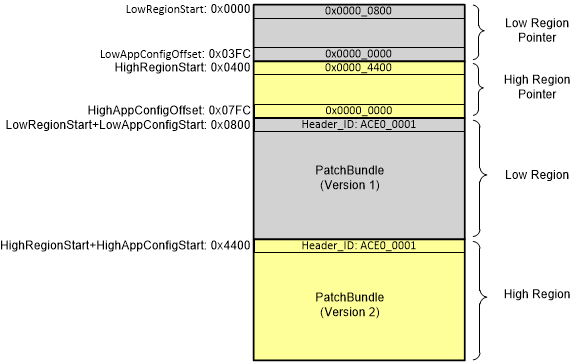 Figure 2-9 State of EEPROM following
UpdateRegionOfEeprom(1) Step 3
Figure 2-9 State of EEPROM following
UpdateRegionOfEeprom(1) Step 3The last step is to erase the LowRegionStart value so that the PD controller can boot from the High Region. The host can use the WriteRegionPointer() functionality as shown in Step 4 of UpdateRegionOfEeprom(1) as illustrated in Figure 2-3. Figure 2-10 shows the memory map after Step 4 is complete. Because the LowRegionStart is now 0, the contents of the Low Region have no impact on how the PD controller boots.
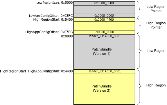 Figure 2-10 State of EEPROM following
UpdateRegionOfEeprom(1) Step 4
Figure 2-10 State of EEPROM following
UpdateRegionOfEeprom(1) Step 4The next time the host must update the EEPROM image the host can execute UpdateRegionOfEeprom(0), and the process can proceed in a similar manner. The host can optionally execute UpdateRegionOfEeprom(0) immediately with the same new Patch Bundle it has just written to the High Region.