SLVAFP0 December 2023 LMR51610
4.2 Loop Response Bench Verification
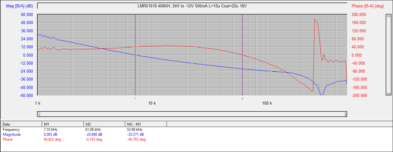
 Figure 4-14 Bode Plot Test Result at
VIN = 24V, VO = -12V, IO = 0.5 A
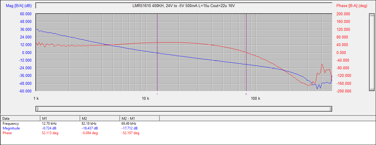
 Figure 4-15 Bode Plot Test Result at VIN = 24V, VO = -5V,
IO = 0.5 A
Figure 4-15 Bode Plot Test Result at VIN = 24V, VO = -5V,
IO = 0.5 ATable 4-1 Loop Test Bench Measurement
Results Summary
| VIN (V) | VO (V) | IO (A) | Measurement Result | ||
|---|---|---|---|---|---|
| fc (kHz) | Gain Margin (dB) | Phase Margin (°) | |||
| 24 | -12 | 0.5 | 7.1 | -20.4 | 40.9 |
| 48 | 12 | 0.5 | 8.44 | -21.2 | 45 |
| 24 | -5 | 0.5 | 12.7 | -18.4 | 52.13 |
| 48 | -5 | 0.5 | 12.7 | -18 | 52.5 |