SLVAFQ4 January 2024 ESD351 , ESDS304 , TPD1E10B06 , TPD4E002 , TPD8E003
Introduction
General purpose input/output, more commonly known as GPIO, is a digital signal pin that can either be configured as an input or output on an integrated circuit. GPIO is a standard interface for a microcontroller to communicate. If GPIO pins are exposed to the outside world, then there is a risk of an electrostatic discharge (ESD) event. The addition of an ESD protection diode is recommended to protect the system against harmful transients. To verify the system is protected properly from any damaging ESD strikes, the characteristics of the GPIO interface must be considered for correct ESD diode selection.
Overview
GPIO pins are common across various systems and applications, and can be used to read values from sensors, control LEDs, and read the state of switches. GPIOs have a low voltage of 3.3 or 5V and require a low voltage ESD protection diode. Depending on the number of GPIO pins that must be protected in the system, a single or multichannel diode can be used.
Causes of ESD
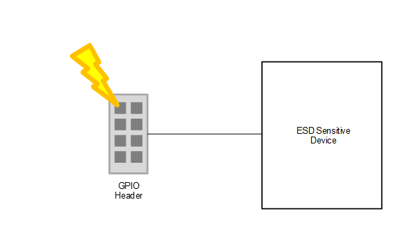
There are many sources of ESD including sliding a plastic container across carpet or removing shrink film from a PCB. This charge can build up and eventually discharge on an exposed connector that is present, including a GPIO header or human interface port. When a connector is in contact with the outside world, the system is at risk of a high voltage strike. This ESD strike or transient event can cause damage to the downstream components in the system.
 Figure 1 GPIO ESD
Event
Figure 1 GPIO ESD
EventESD Protection Requirements
To protect GPIOs, follow the list of parameters:
- Working
Voltage
- The reverse working voltage (VRWM) of the protection diode must be greater than or equal to the operating voltage of the system that is protected. For GPIO pins, the typical operating voltage range is between 3.3V and 5V. This translates to a working voltage of greater than or equal to 3.3V to 5V.
- Polarity
- A unidirectional or bidirectional diode can be used to protect the system. Unidirectional diodes are recommended when there is only a positive voltage on the line. Unidirectional diodes also clamp at a lower voltage for negative ESD strikes which is an advantage when the application has a low tolerance to negative voltage strikes. Bidirectional diodes are recommended when there can be either positive or negative voltages.
- Clamping
Voltage
- The clamping voltage is dependent on the nearest downstream circuitry and is recommended to be less than the absolute maximum voltage of the device pins. In this case, the downstream circuitry is most likely a microcontroller which has the absolute maximum voltage specified in the data sheet.
- Capacitance
- Since the frequencies can vary depending on the microcontroller or device with the GPIO pins, the capacitance can also have a range. A general rule is speeds up to 10Mbps require a capacitance less than 20pF and speeds that reach up to 500Mbps require a capacitance less than 4pF.
- IEC 61000-4-2
Rating
- Real-world ESD strikes are defined by the IEC 61000-4-2 testing standard. This standard consists of two measurements: contact and air-gap discharge. The higher the contact and air-gap rating, the higher the voltage a device can withstand. For GPIO pins, a minimum IEC 61000-4-2 rating of 8kV for contact and 15kV for air-gap is recommended.
Table 1 lists device that support these specifications.
Selecting an ESD Diode for GPIO Applications
The first step in selecting an ESD diode is the system requirements. For this example, the system is a 3.6V microcontroller with an absolute maximum voltage of 6V, only positive voltages, and eight GPIO pins that require protection. Based on the system requirements, the working voltage of the diode can be 3.6V. Since only positive voltages are seen on the line, a unidirectional diode is recommended. An absolute maximum voltage of 6V causes the diode to have a clamping voltage less than six. With eight GPIO pins needing protection, a multichannel device is recommended but eight single channel devices can also meet the requirements. An example is shown below using ESDS304 as the protection diode that meets the above requirements.
 Figure 2 GPIO
Application
Figure 2 GPIO
ApplicationESDS304 was selected for protection because the device met the system requirements. When selecting an ESD diode for GPIO or any application, considering the system requirements is required to properly protect the circuitry.
Summary
GPIO pins require ESD protection to survive real-world ESD strikes. Selecting the correct protection diode is crucial in maintaining system functionality and coverage in the event of a high voltage transient. Table 1 lists device recommendations for protecting GPIO pins, and more devices can be found here.
| Device | VRWM (V) | IEC 61000-4-2 (kV) (Contact/Air-gap) | Channel Count | Polarity | Package Size (mm) |
|---|---|---|---|---|---|
| ESD351 | 3.6 | 30/30 | 1 | Unidirectional | DFN1006 (1.00 × 0.60) |
| ESDS304 | 3.6 | 30/30 | 4 | Unidirectional | SOT-23 (2.90 × 2.80) |
| TPD8E003 | 5.5 | 12/15 | 8 | Unidirectional | WSON(1.60 × 1.35) |
References
- Texas Instruments, System-Level ESD Protection Guide, marketing selection guide.
- Texas Instruments, Reading and Understanding an ESD Protection Data Sheet, user's guide.
- Texas Instruments, ESD Packaging and Layout Guide, application note.