SLVAFR6 January 2024 LM5067
2 The External Auxiliary Power Supply and Op Amp Follows and Changes the UVLO Swing Amplitude of LM5067
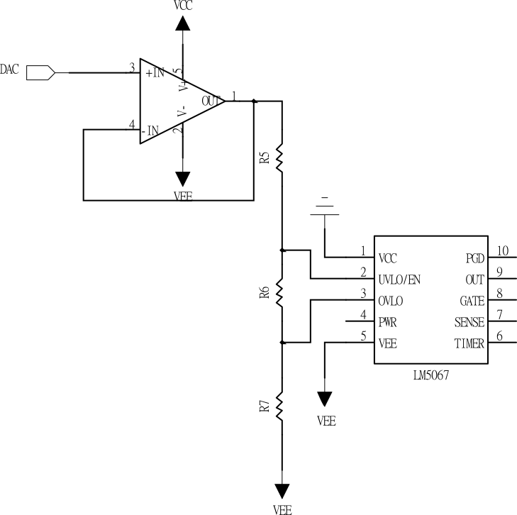
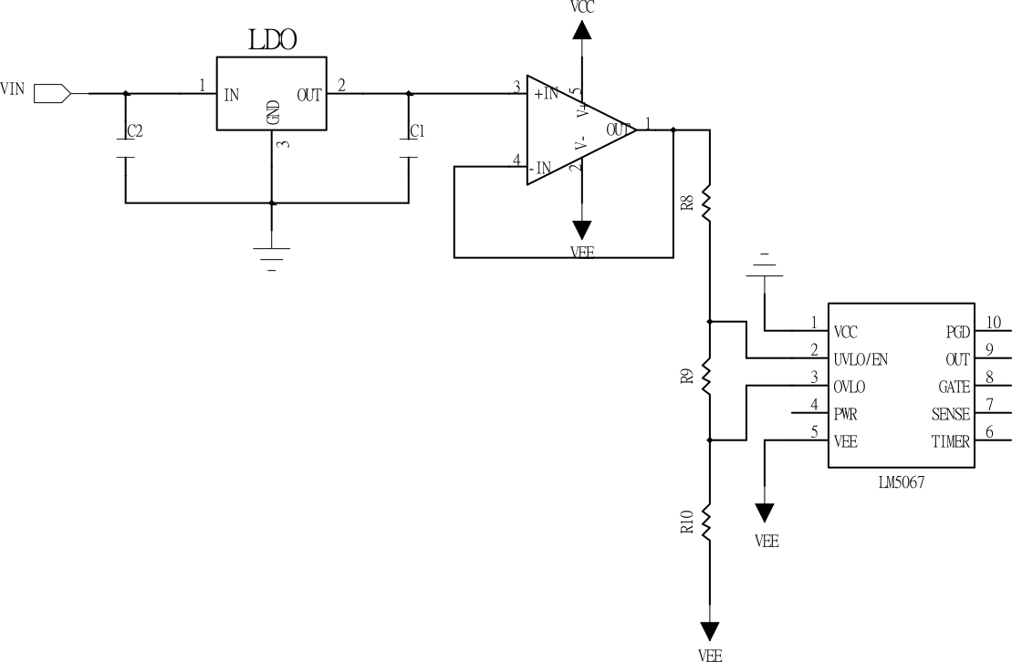
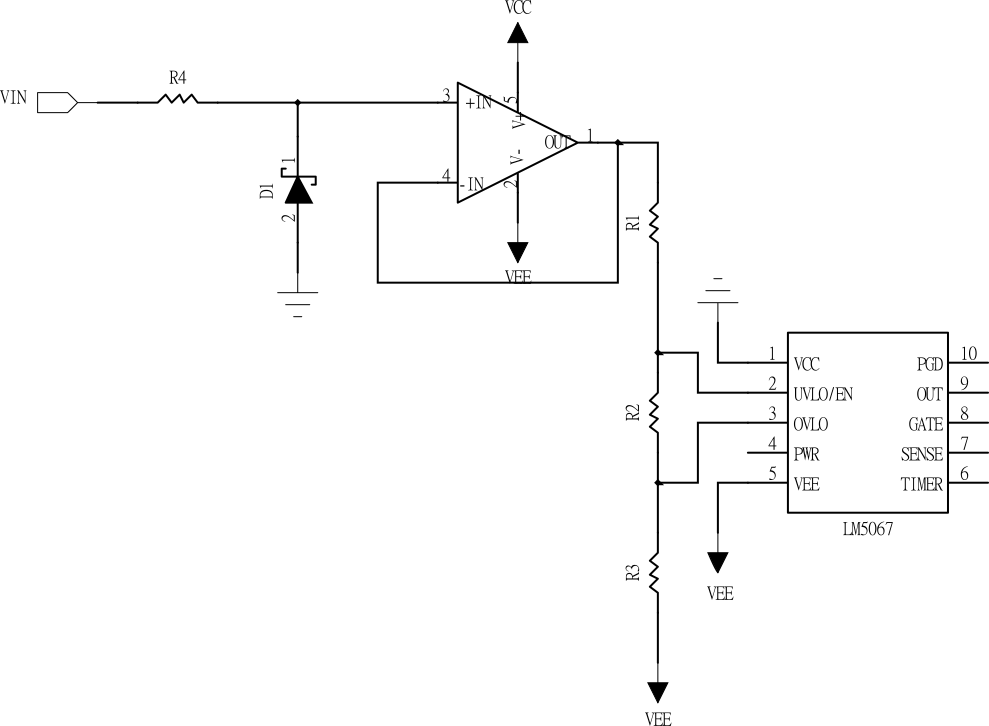
As shown in Figure 2-1, Figure 2-2, and Figure 2-3, the external auxiliary power supply can use a regulated diode, an external DAC, LDO, and other available power supplies and follow through the op amp, you can output an adjustable power supply VS, and the adjustable power supply VS is added to the voltage divider resistor. The voltage setpoint of the UVLO Pin can be expressed as Equation 2.
For the LM5067 to work properly, set the LM5067 to 2.5V. UVLOMIN when the voltage dynamic range of VS-VEE is R. The voltage swing range of UVLO Pin can be expressed as Equation 3.
Taking VS as the independent variable, the derivative of Equation 3 can be obtained and expressed as Equation 4.
Therefore, if the resistor-to-voltage ratio is a fixed value, the maximum voltage of the UVLO pin can be reduced by increasing the VS.
 Figure 2-1 Set LM5067 UVLO With External
DAC
 Figure 2-2 Set the LM5067 UVLO With
External LDO
 Figure 2-3 Set the LM5067 UVLO With
External Zener Diode