SLVAFT1 September 2024 TPS92633-Q1
2.2.2 Single-LED-Short Auto-Recovery
After the single-LED-short fault is asserted and the devices starts, an auto-recover process. During retrying, the device sources full current from IN to OUT to pull up the LED loads every 10ms for 300us period when the PWM input is logic high for the faulty channel. Once the device detects V(OUTx) risng above V(SLS_th_rising), the single-LED-short fault is cleared and the device resumes to normal operation automatically. The V(SLS_th_rising) is 2.5% higher the V(SLS_th_falling), therefore, it can be easily obtained according to Equation 5. The total retry current I(Retry_Tot) is the addition of the retry currents of the paralleled channels, which can be calculated from Equation 7.
Where
- I(Retry_Out1) is the retry current of channel 1.
- I(Retry_Out2) is the retry current of channel 2.
- I(Retry_Out3) is the retry current of channel 3.
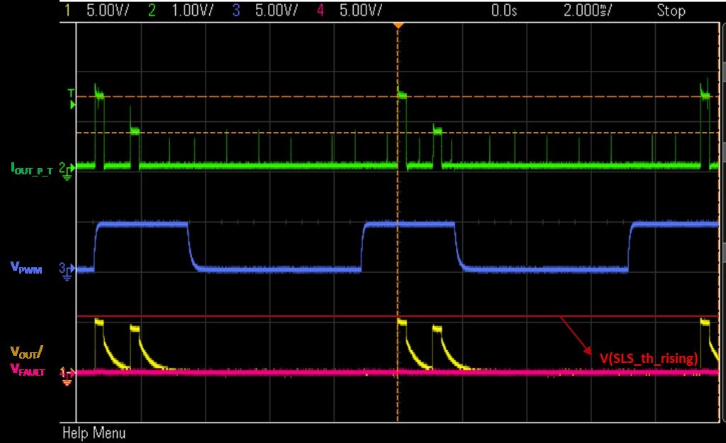
In this high current application, there is a special situation if PWM dimming feature is required. Since the fault detection and auto-retry processes for each channel are independent, if all three channels are working in PWM mode, the time difference of each channel can be accumulated with more PWM cycles, eventually leading to a possibility that the retry current of each channel becomes out of sync when PWM is operating for a long time with a high PWM frequency, which is shown in the Figure 2-2. The output voltage triggered by this out-of-sync retry current cannot rise above the designed V(SLS_th_rising), in this situation, the device cannot be able to recover even the single-LED-short fault is removed. To make sure the desired behavior of auto-recovery, the retry current of all channels needs to be synchronized to maintain a full retry current and meet the threshold setting, there are some steps that need to be considered during the design process.
 Figure 2-2 Out of Sync Retry Currents
Step 1: Evaluate the V(SLS_th_rising)
Set V(SLS_th_rising) to a level in which the device can recover under the situation of out-of-sync retry currents.
Considering the worst case - the retry current of the three channels are completely separated. In this condition, the retry current of single channel needs to be used in the calculation. In addition to meet the Equation 6, the V(SLS_th_rising) needs to be within the bounds of the following Equation 8.
The equation means that the threshold must be lower than the forward voltage of the LED string at the given retry current of single channel. If the calculation can be applied under any circumstance, the device is able to work normally. But if the evaluation results show that the target range is difficult to achieve, the step 2 needs to be followed.
Step 2: Recommended External Circuit to Sync All Retry Currents
According to the auto-recovery mechanism, the device retries the LED load every 10ms for 300us period until the fault is removed. To avoid the accumulation of time difference, a wait synchronization interval of no less than 10ms is designed to synchronize the retry current of different channels.
The synchronization can be easily accomplished by controlling PWM pins and FAULT pin. After a single-LED-short fault is reported out, the PWM pins are pulled low for a certain time interval, then the PWM inputs can be held high until the fault is removed and the FAULT pin is released. The designed waveforms are depicted in Figure 2-3. In this way, time differences are not introduced with PWM cycles during the fault state.
 Figure 2-3 Designed Waveforms to Sync all
Retry Currents
Figure 2-3 Designed Waveforms to Sync all
Retry CurrentsA recommended synchronization circuit to sync all retry current is shown in Figure 2-4.
 Figure 2-4 Recommended Synchronization
Circuit for TPS92633-Q1 Parallel Channels
 The FAULT pin is internally pulled low when the device detects a single-LED-short fault, due to the presence of the diode, the PWM pins can be clamped to a low voltage level until Q1 is turned off, the PWM pins return to a constant high voltage level after a designed discharge time. Once this fault is cleared, the device detects the output voltage rising above V(SLS_th_rising), the FAULT pin is released and the device resumes to normal operations.
To make sure the circuitry can work as expected, the pullup resistor R1 must be large enough that can cover the range of Vbat and keep the FAULT pin is always below 0.4V when fault is triggered, otherwise the FAULT pin can not be pulled down correctly. In addition, the R2 and C1 need to be chosen appropriately for the given threshold voltage of Q1 and the designed PWM pull-low time interval.