SLVU179B October 2006 – February 2022 TPS51117
3 Performance Data and Typical Characteristic Curves
Figure 3-1 through Figure 3-6 present typical performance curves for TPS51117EVM-001.
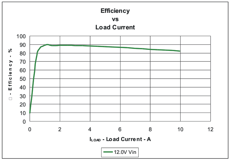 Figure 3-1 Efficiency
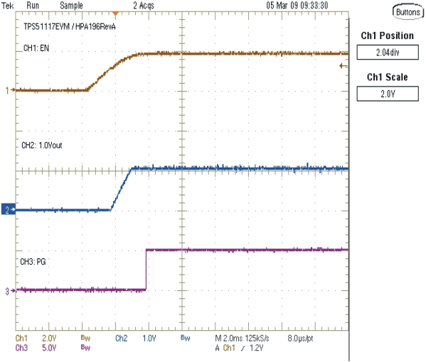 Figure 3-3 Enable Turn-On (12
VIN, 1.05 V/10 A)
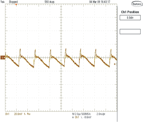 Figure 3-5 Output Ripple (12 VIN, 1.05 V/10 A)
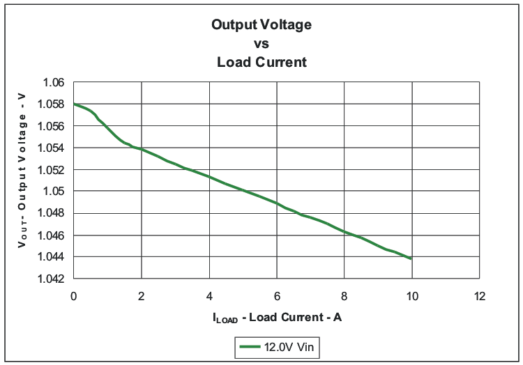 Figure 3-2 Load Regulation
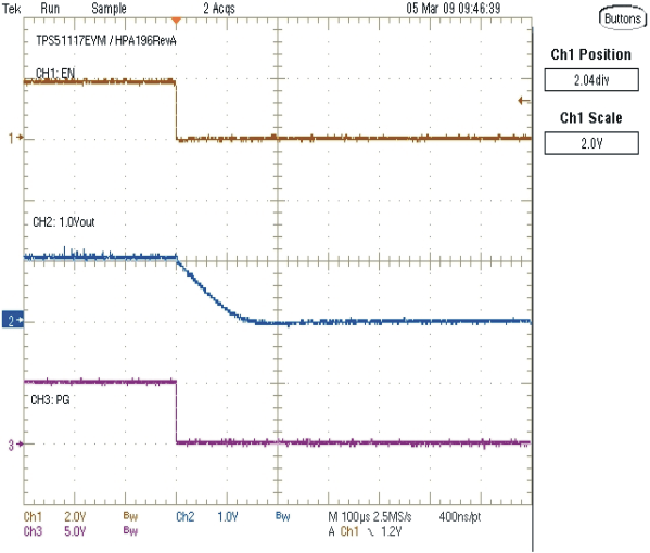 Figure 3-4 Enable Turn-Off (12
VIN, 1.05 V/10 A)
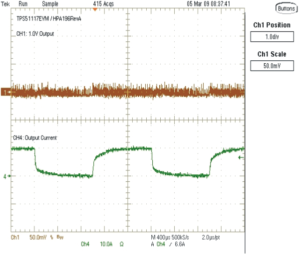 Figure 3-6 Load Transient (12
VIN 1.05 V/0 A–10 A)