SLVUB62B June 2017 – November 2020
- Trademarks
- 1 About this Manual
- 2 Information About Cautions and Warnings
- 3 Items Required for Operation
- 4 Introduction
-
5 Setup
- 5.1
Switch, Push Button, Connector, and Test Point Descriptions
- 5.1.1 Power Path Jumper Configuration
- 5.1.2 DP Source Receptacle
- 5.1.3 S1 HRESET Push-Button
- 5.1.4 S6 SPI MISO Pull Down Button
- 5.1.5 S3: FTDI Enable and Disable
- 5.1.6 S2: SPI , I2C, and BusPowerZ Configurations
- 5.1.7 J1: Barrel Jack Power Connector
- 5.1.8 Barrel Jack Detect
- 5.1.9 USB Type B Connector (J11)
- 5.1.10 USB Type-CConnector (J2)
- 5.1.11 USB Micro B Connector (J9)
- 5.1.12 TP13 (5 V), TP8 (3.3 V), and TP12 (1.2 V)
- 5.1.13 Aardvark Connector (J10)
- 5.1.14 TP10, TP11, TP15, TP16, TP17, TP18, TP9: GND Test Points
- 5.1.15 TP1, TP2, TP3 and TP4 – CC1 and CC2 Test Points
- 5.1.16 TP14 (PA and PB): VBUS Test Point
- 5.1.17 TP7, TP6, and TP5: A-VAR, B-VAR, and System Power Test Points Respectively
- 5.1.18 J3 and J4 (Bottom of EVM): Signal Headers
- 5.2 LED Indicators Description
- 5.1
Switch, Push Button, Connector, and Test Point Descriptions
- 6 Using the TPS65988EVM
- 7 Connecting the EVM
- 8 REACH Compliance
- 9 TPS65988EVM Schematic
- 10TPS65988EVM Board Layout
- 11TPS65988EVM Bill of Materials
- 12Revision History
7.1.3.1 Required Hardware
The following hardware is required to test the DP alternate mode and USB 3.0:
- A Microsoft®Windows® PC with a USB
Type-A receptacle and DisplayPort video output
- USB 2.0 or USB 3.0 Type-A to Type-B cable
- USB 2.0 or USB 3.0, or USB Type-C flash drive
- USB 2.0 Type-A to micro USB cable
- USB Type-C cable
- Monitor with DisplayPort Input
- Mini DisplayPort to DisplayPort cable or USB Type-C to DisplayPort cable
- FTDI board (used for programming the TPS695988EVM and interfacing with configuration tool)
- Dell laptop power supply (model # 492-BBGP)
Use the TPS65988EVM to test DP alternate mode as well as USB data using the default firmware. To do so, connect a DP source from a laptop to the TPS65988EVM through the DP receptacle on the EVM. Next, connect a USB Type-B to USB Type-A cable from the TPS65988EVM to a Windows computer. To test DP, connect a USB Type-C to DP cable from one of the USB Type-C ports to a DP monitor. To test USB functionality, connect a USB Type-C flash drive to the other USB Type-C port on the TPS65988EVM. The monitor displays what is present from the DP source. The flash drive enumerates on the windows PC. Table 7-1 explains this test setup.
| Test Setup | Pass Criteria | ||||
|---|---|---|---|---|---|
| DP can be connected from port A/B with a USB Type-C to DP cable. | 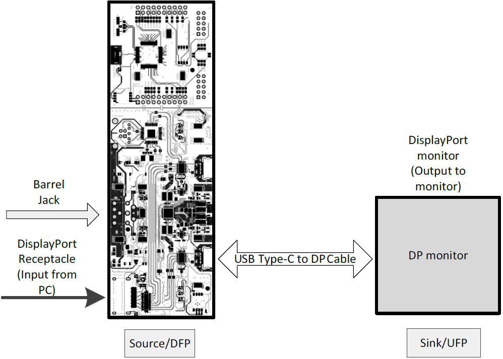 | ||||
| USB can be connected to Port A/B directly with a Type-C Flash Drive | 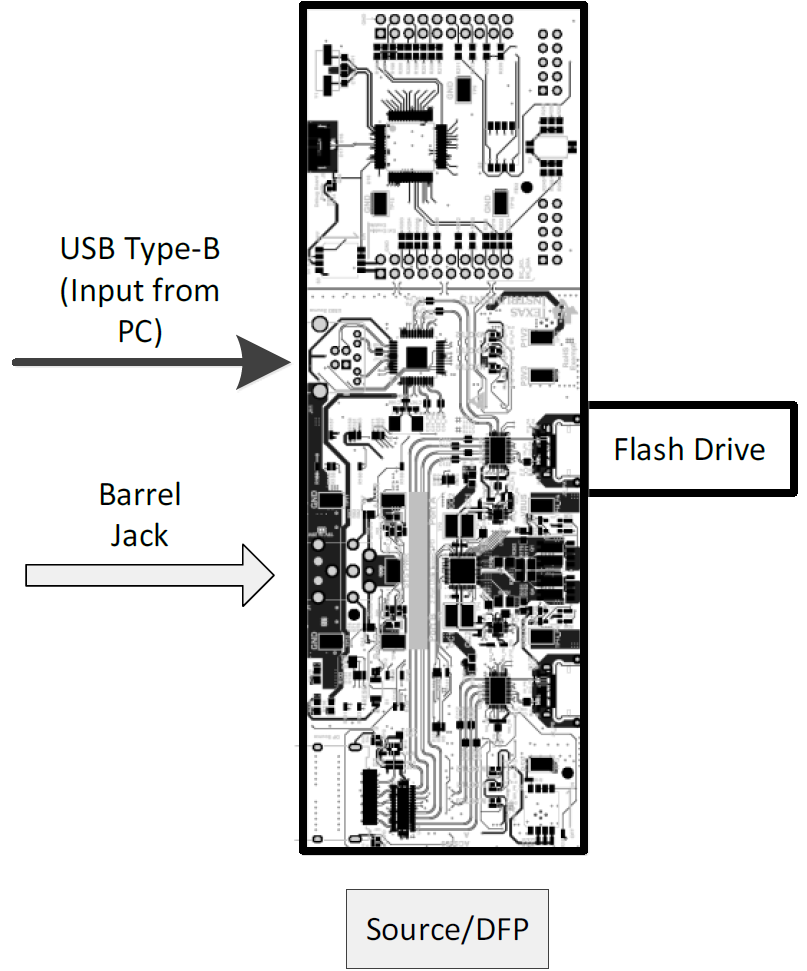 | ||||
| Connect a type C cable from DP and USB can be tested simultaneously with the TPS65988EVM setup to the right. | 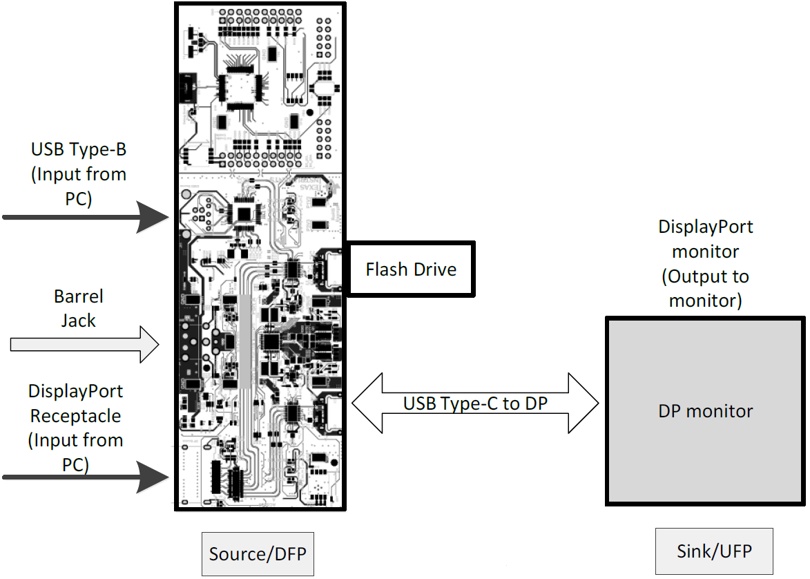 | ||||
| Observe TPS65988EVM LEDs. | LED Name | Event Mapping | Source x988 LED Status | ||
| MXCTL0 | USB3 | ON | |||
| MXCTL1 | DP | ON | |||
| MXCTL2 | POL | ON/OFF | |||
| HPD | X | ON | |||
| Variable DC/DC | X | A/B ON | |||
| Check for video on DP monitor and verify USB flash drive enumerates on the PC. | Successfully copy and paste a file to and from the USB flash drive. Extend the PC to the DP monitor and play video to verify video stream. | ||||
| Verify the voltages on the DP source board. | |||||
| Source Test Point | Test Point Name | Voltage | |||
| TP12 | P1V2 | 1.2 V | |||
| TP8 | P3V3 | 3.3 V | |||
| TP13 | P5V | 5 V | |||
| TP5 | SYS_PWR | 20 V | |||
If video is displayed on the monitor, it is confirmed that DP alternate mode is entered. Similarly, if the USB flash drive can be read by the attached PC, it is confirmed that USB data is functioning properly. USB 3.0 data can be confirmed by observing LED MUX_CTRL0 in the high state.