All trademarks are the property of their respective owners.
The LM5127EVM-FLEX is designed for use with a wide input voltage range of 3 V to 42 V to produce two tightly regulated output voltages of 5 V at 5 A and 3.3 V at 7 A. Figure 1-1 shows the standard configuration of the LM5127EVM-FLEX. It is configured as a typical front end power supply in 12 V automotive applications. Channel 1 implements a synchronous pre-boost, supplying adequate voltage for the two synchronous buck controllers (channel 2 / channel 3) to maintain output regulation for input voltage transients as low as 3 V. The free-running switching frequency is 440 kHz and synchronization to an external clock signal is possible at higher or lower frequency. The main discrete power-train components (inductors and MOSFETs) are automotive AEC-Q200 rated.
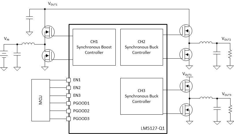
The LM5127EVM-FLEX has the following features :
Table 2-1 shows the evaluation module characteristics in the standard configuration and according to Section 6.
Parameter | Test Condition | MIN | TYP | MAX | UNIT | |
---|---|---|---|---|---|---|
INPUT VOLTAGE CHARACTERISTICS | ||||||
Input voltage range | Operation | 3 | 18 | V | ||
Start-up | 5 | V | ||||
Transient | 42 | V | ||||
Input current, no load | VEN1
= VEN2 = VEN3 = 5 V IOUT1 = IOUT2 = IOUT3 = 0 A VCH1A = 13.5 V, VCCX = VOUT2, VDDX = VOUT3, CFG/MODE = tied to AGND | VIN = VCH1A = 9 V | 50 | μA | ||
VIN = VCH1A = 12 V | 50 | μA | ||||
VIN = VCH1A = 18 V | 50 | μA | ||||
Input current shutdown | VEN1 = VEN2 = VEN3 = 0 V | VIN = VCH1A= 13.5 V | 4 | μA | ||
CHANNEL 1 OUTPUT CHARACTERISITICS (Pre-boost) | ||||||
Output voltage (VOUT1) | 6.9 | V | ||||
Maximum output current (IOUT1) |
VCH1A > 3 V |
10 |
A | |||
CHANNEL 2 OUTPUT CHARACTERISITICS (SINGLE BUCK) | ||||||
Output voltage (VOUT2) |
5 |
V | ||||
Maximum output current (IOUT2) | VCH1A > 3 V |
5 |
A | |||
CHANNEL 3 OUTPUT CHARACTERISITICS (SINGLE BUCK) | ||||||
Output voltage (VOUT3) | VCH1A > 3 V |
3.3 |
V | |||
Maximum output current (IOUT3) |
7 |
A | ||||
SYSTEM CHARACTERISITICS | ||||||
Switching Frequency | VCH1A = 13.5 V |
440 |
kHz | |||
Half Load Efficiency (ηHALF) |
IOUT2 = 2.5 A, IOUT3 = 3.5 A | VCH1A = 9 V |
95.3 | % | ||
VCH1A = 13.5 V |
94.2 | % | ||||
VCH1A = 18 V |
92.8 | % | ||||
Full Load Efficiency (ηFULL) | IOUT2 = 5 A, IOUT3 = 7 A (ADD table note | VCH1A = 9 V |
94.5 | % | ||
VCH1A = 13.5 V |
93.8 | % | ||||
VCH1A = 18 V |
92.1 | % |
|
CAUTION: Prolonged operation with low input at full power
will cause heating of Q1 and Q2.
Board surface is hot. Do not touch. Contact may cause burns. |