SLVUC17 August 2021 TPS7H2211-SP
1.1 Default Board Configuration
The EVM is designed to be used across the entire input voltage and output current range of the TPS7H2211-SP while providing flexibility to configure the device to operate under different conditions. By default, the EVM is configured for a single device as summarized in Table 1-1, but the board provides footprints that can be populated with an additional device and passive components to allow for testing of parallel or cold sparing applications.
More detailed information about the default EVM configuration can be found in the Default Configuration Schematic and the Default Configuration Bill of Materials.
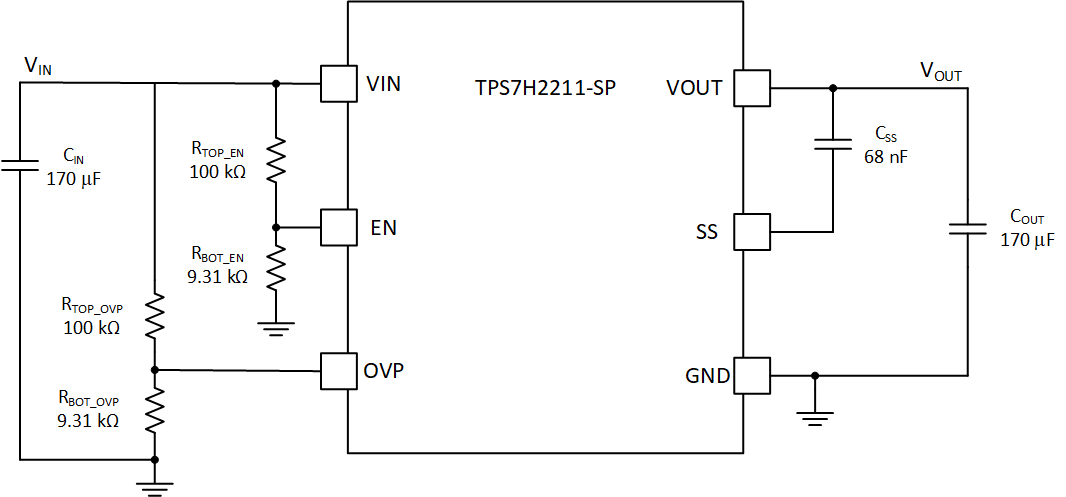
 Figure 1-1 Default Configuration Simplfied Schematic
| Specification | Value | Description |
|---|---|---|
| Input Voltage VIN | 12 V | Falls within the recommended device input voltage range of 4.5 V to 14 V. |
| Output Current IOUT | 0 to 3.5 A | Does not exceed maximum device continuous switch current of 3.5 A per device. |
| EN Turn-on Voltage VINEN_RISE | 7.4 V | Typical EN turn-on and turn-off values. Set by:R1 (RTOP_EN) = 100 kΩ R4 (RBOT_EN) = 9.31 kΩ |
| EN Turn-off Voltage VINEN_FALL | 6.1 V | |
| OVP Enter Voltage VINOVP_RISE | 13.5 V | Typical OVP enter and exit values. Set by: R3 (RTOP_OVP) = 100 kΩ R5 (RBOT_OVP) = 9.31 kΩ |
| OVP Exit Voltage VINOVP_FALL | 13.4 V | |
| Soft Start Time tSS | ~10 ms | Typical time to go from 10% to 90% of the final voltage. Set by: C1 (CSS) = 68 nF |