SLVUC32B June 2021 – February 2022 DRA829J , DRA829J-Q1 , DRA829V , DRA829V-Q1 , TDA4VM , TDA4VM-Q1 , TPS6594-Q1
- Trademarks
- 1Introduction
- 2Device Versions
- 3Processor Connections
- 4Supporting Functional Safety Systems
-
5Static NVM Settings
- 5.1 Application-Based Configuration Settings
- 5.2 Device Identification Settings
- 5.3 BUCK Settings
- 5.4 LDO Settings
- 5.5 VCCA Settings
- 5.6 GPIO Settings
- 5.7 Finite State Machine (FSM) Settings
- 5.8 Interrupt Settings
- 5.9 POWERGOOD Settings
- 5.10 Miscellaneous Settings
- 5.11 Interface Settings
- 5.12 Multi-Device Settings
- 5.13 Watchdog Settings
- 6Pre-Configurable Finite State Machine (PFSM) Settings
- 7Impact of NVM Changes
- 8References
- 9Revision History
6.3.1 TO_SAFE_SEVERE and TO_SAFE
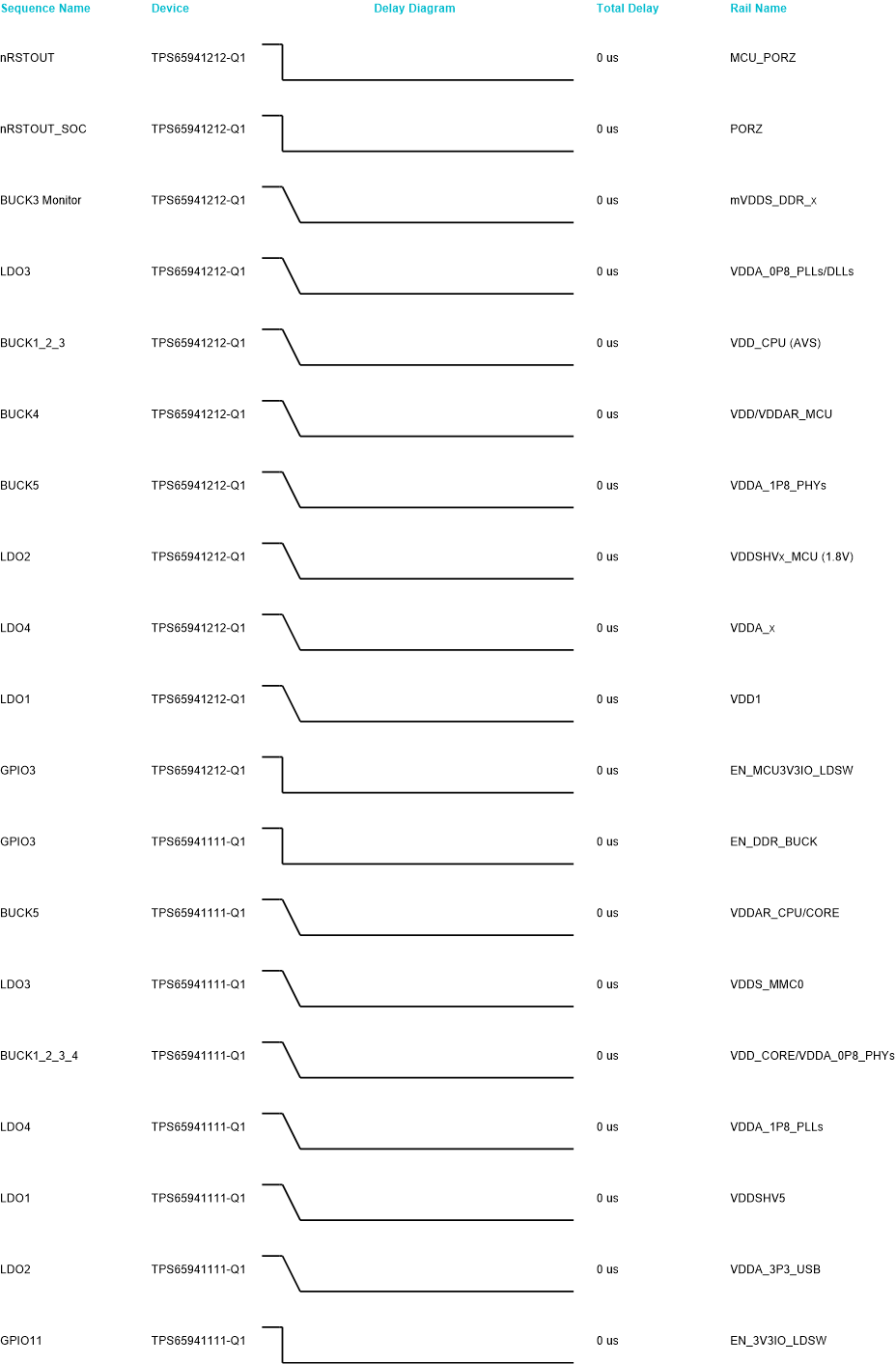
The TO_SAFE_SEVERE and TO_SAFE are distinct sequences which occur when transition to the SAFE state. Both sequences shut down all rails without delay. The TO_SAFE_SEVERE sequence immediately ceases BUCK switching and enables the pulldown resistors of the BUCKs and LDOs. This is to prevent any damage of the PMICs in case of over voltage on VCCA or thermal shutdown. The timing is illustrated in Figure 6-2. The TO_SAFE sequence does not reset the BUCK regulators until after the regulators are turned off as shown in Figure 6-2.
 Figure 6-2 TO_SAFE_SEVERE and TO_SAFE
Power Sequence
Figure 6-2 TO_SAFE_SEVERE and TO_SAFE
Power SequenceAfter the power sequence shown in Figure 6-2, the TO_SAFE sequence delays the TPS65941212 by 16 ms and the TPS65941111 by 3 ms. This ensures that the primary PMIC finishes after the secondary. After these delays, the following instructions are executed on both PMICs:
//TPS65941212 and TPS65941111
// Clear AMUXOUT_EN, CLKMON_EN, set LPM_EN
REG_WRITE_MASK_IMM ADDR=0x81 DATA=0x04 MASK=0xE3
// Reset all BUCK regulators
REG_WRITE_MASK_IMM ADDR=0x87 DATA=0x1F MASK=0xE0
The TO_SAFE_SEVERE sequence executes the following instruction after the power sequence:
//TPS65941212 and TPS65941111
// Clear AMUXOUT_EN, CLKMON_EN, set LPM_EN
REG_WRITE_MASK_IMM ADDR=0x81 DATA=0x04 MASK=0xE3