SLVUC36 April 2021 TPS23882B
- Trademarks
- 1Description
- 2Quick Start
- 3General Use Features
- 4TPS23882B1 GUI Setup
- 5EVM Schematic, Layout Guidelines, PCB Assembly and Layer Plots
- 6Bill of Materials
4.3.1 Basic CCS and Terminal Setup
Use the following steps for basic CCS and terminal setup:
- Launch the CCS program on the PC: Start → Texas Instruments → Code Composer Studio 7.2.0 → Code Composer Studio 7.2.0.
- OK the workspace location and CCS starts.
- Import the project: Project→ Import CCS Projects (make sure you are in CCS Edit mode).
- Navigate to the project location, then click the Finish button.
- Build the project by clicking the hammer symbol. Semi-Auto or Auto mode can be switched selected using the drop-down arrow to the right of the hammer symbol.
- Launch the debug session from CCS to activate the current project: Run, Debug (or F11).
- Run the active project: Run, Resume (or play button, F8).
- Determine the PC COM port connected to the LaunchPad by going into the Device Manager Ports (COM and LPT) section. Launch the terminal program.
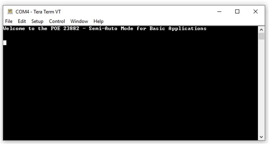
- Once the terminal program is properly connected to the LaunchPad running the PoE firmware, then text similar to the following image appears.
 Figure 4-6 Semi-Auto UART Transmission Startup
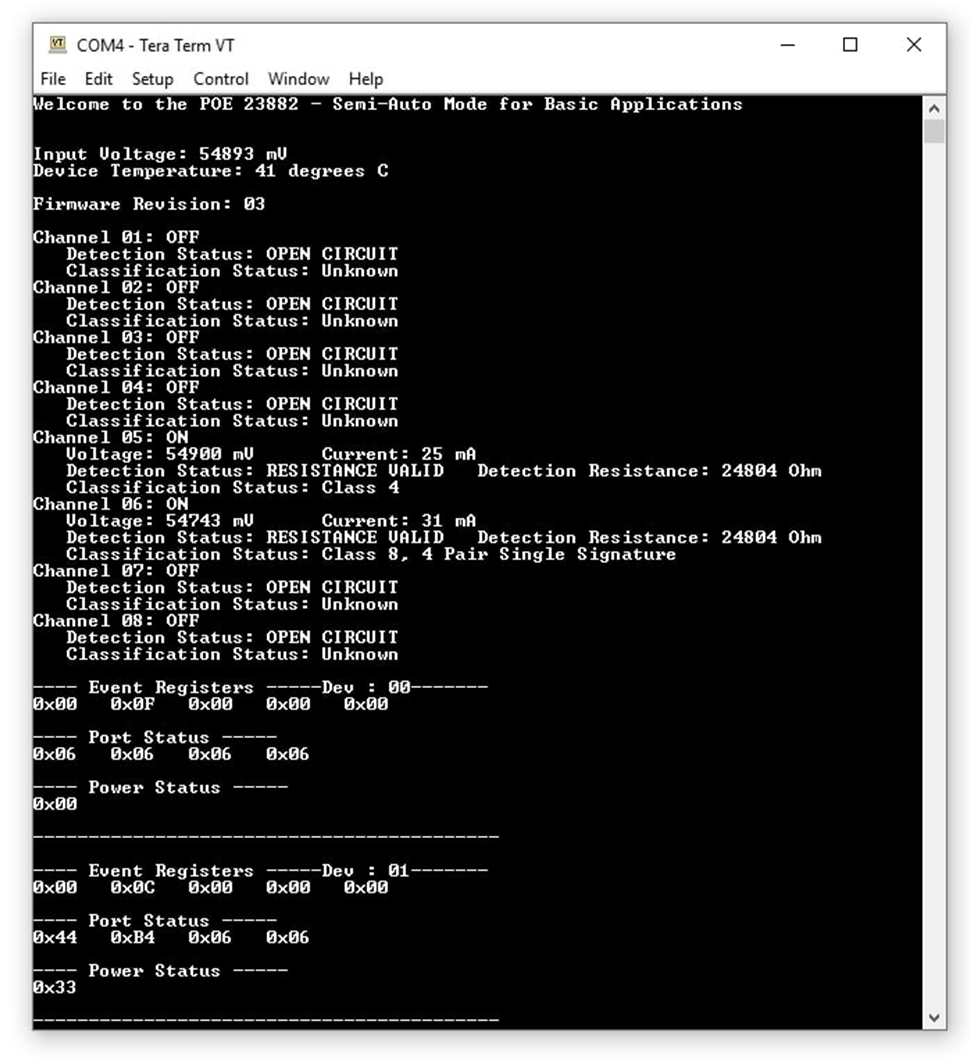
 - The TPS23882B1 is now waiting for a PD load to be installed. As ports are installed, the system automatically detects, classifies, and powers up the port as shown in Figure 4-7. Port status is updated on the screen approximately every 10 seconds.
 Figure 4-7 Semi-Auto UART Transmission Status