SLVUCG3A September 2022 – March 2023 TPSM33625
4 Schematic
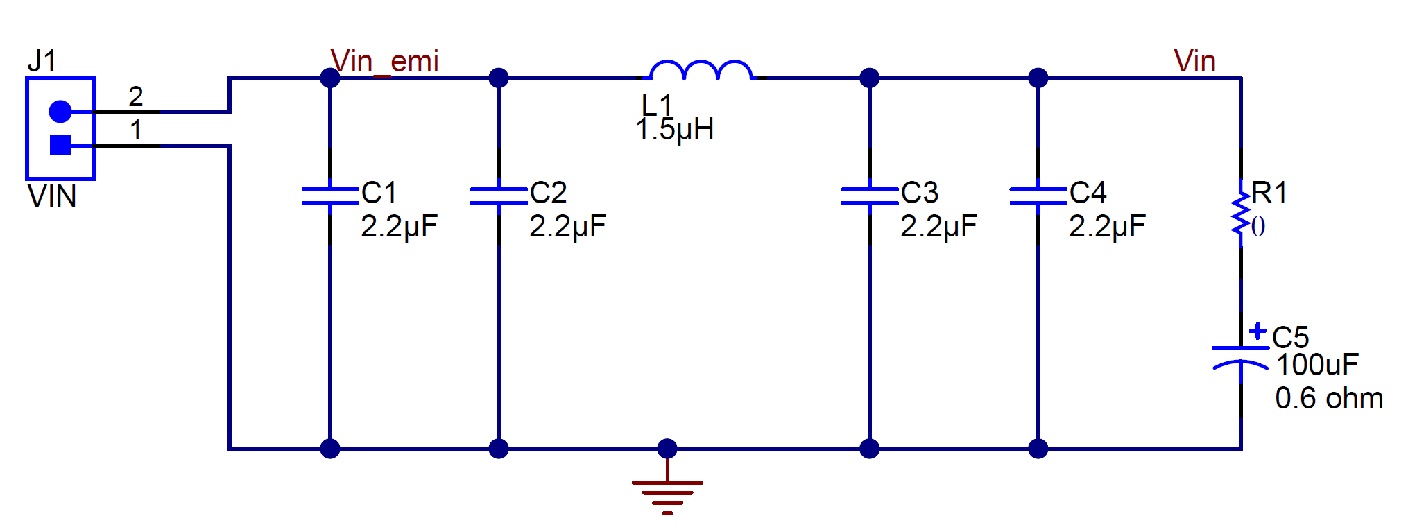
Customers can choose to implement a PI filter in series with the input of a power regulator, which allows for the differential noise generated to be attenuated, allowing a noise emission regulation to be met. The filter crossover frequency is designed for 1-MHz switching frequency, attenuating the switching frequency and the corresponding harmonics greatly. A damping capacitor is provided (C5), to damp the high-Q PI filter. For more information on filter damping, see Section 8.
 Figure 4-1 Schematic-Compliance Testing Filter
In the buck schematic, the difference between the TPSM33625EVM and TPSM33625FFEVM is the REFDES=U1 device part number. Use a buck schematic with additional feedback resistors to program the output voltage and add a placeholder for additional output capacitance to achieve stability or meet a output transient specification with pin definition RT (adjustable frequency) or Mode/Sync (mode select or synchronization) differing.
 Figure 4-2 Schematic (TPSM33625EVM) – TPSM33625
 Figure 4-3 Schematic (TPSM33625FEVM) – TPSM33625F
A disable, frequency select, and output voltage select jumper are provided to aid the evaluation. Additionally, test points to evaluate product features and stability are provided.
 Figure 4-4 Schematic (TPSM33625EVM) – Configuration Jumpers and Evaluation Test Points
A disable, mode select or synchronization, and output voltage select jumper are provided to aid the evaluation. Additionally, test points to evaluate product features and stability are provided.
 Figure 4-5 Schematic (TPSM33625FEVM) – Configuration Jumpers and Evaluation Test Points