SLVUCP8 September 2024 TPS26750
- 1
- Description
- Get Started
- Features
- Applications
- 6
- 1Evaluation Module Overview
- 2Hardware
-
3Software
- 3.1 Software Description
- 3.2 Software Installation
- 3.3 Software Development
- 3.4 Using the Application Customization Tool
- 4Application Specific Use Cases
- 5Hardware Design Files
- 6Additional Information
2.3 Setup
The following incorrect silk screen printing on the A2 revision of the TPS26750EVM must be noted:
- The silk screen label for J11 is partially incorrect. Jumper J11 is located underneath the silk screen text VIN3V3 EN near the center of the board. The jumper is used for disabling the LDO that provides 3.3V to pin VIN_3V3 of the TPS26750. However, to the left of Jumper J11, J12 is printed, which is incorrect. J11 needs to be printed instead.
- The silk screen label for J12 is partially incorrect. Jumper J12 is located underneath the silk screen text PP5V_EN near the center of the board. Jumper J12 is used for disabling the switch that provides 5V to pin PP5V of the TPS26750. However, to the right of Jumper J12, J11 is printed, which is incorrect. J12 needs to be printed instead.
- VBUS_D10 on header J5 is incorrectly labeled on the silk screen as VBUS_LV_D10.
- VBUS_LV_D10 on header J5 is incorrectly labeled on the silk screen as VBUS_D10.
All references in this document to the respective jumpers and signals above are made in reference to the actual location, and not to the location inferred by the incorrect silk screen printing.
Out of the box, the TPS26750EVM is configured for 15W (5V/3A) sourcing and 240W (48V/5A) sinking, utilized through the DUT Type C connector (J4). If a different configuration is required, then utilize the Application Customization Tool to create and/or load a different configuration. For detailed instructions on how to use the Application Customization Tool (also used interchangeably with the term GUI throughout this document), refer to Section 3.
Flashing Firmware Configuration to the TPS26750EVM

Figure 2-2 EVM Flashing Block Diagram
Required hardware setup:
- Ensure jumper J11 (erroneously labeled as J12 on EVM) is connected.
- Connect USB-C end of USB-C to USB-C cable or USB-A to USB-C cable to Data Type C port (J6).
- Connect other end of cable to computer.
When flashing a new configuration to the TPS26750EVM, the binary configuration file is written to U13, the EEPROM. More details are provided in Section 3.4.6.3.
Stand Alone Testing
 Figure 2-3 Stand Alone Testing Block
Diagram
Figure 2-3 Stand Alone Testing Block
DiagramSupported functionality as a stand alone device:
- 5V sourcing (DFP)
- 5 - 48V sinking, both SPR and EPR capable (UFP)
- 5V sourcing, 5V to 48V sinking (DRP)
To test the TPS26750EVM as a stand-alone device, users need to connect a power source to the Power Type C connector (J3) or one of the XT30 Power connectors (J1 or J8).
If users want to support 5V sourcing, then the power supply needs to provide at least 18W of power, due to the following board requirements:
- 5V/3A for PP5V Power Path
- 5V/120mA for VCONN
- 5V/100mA for Board MCU (U22)
If users only want to support a powered sinking setup, then 5W is all that is required to be provided to the Power Type C port (J3). When sinking, the output of the sinking power path can be accessed from the XT30F (PPHV) connector (J7). The portions of the EVM are powered, highlighted in red, when testing the device in Stand Alone mode and are shown in Figure 2-3.
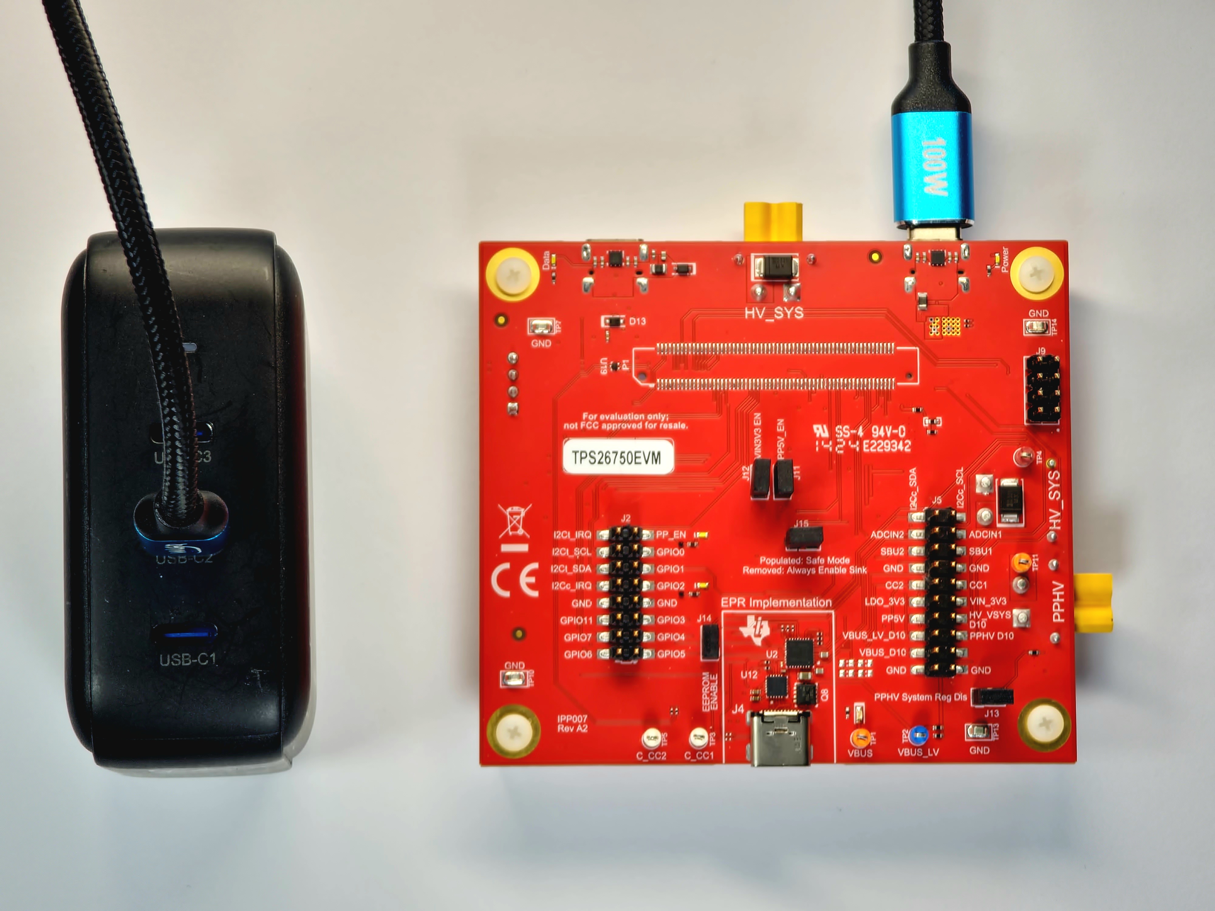
The example setup in Figure 2-4 shows the Aergiatech 140W 3 Port PD3.1 Supported Wall Adapter, whose USB-C2 port is capable of providing 100W (20V at 5A) of power, connected to a USB-C to USB-C 100W capable cable, which is in turn connected to the Power Type C port (J3) of the TPS26750EVM. This example setup is capable of sourcing 5V of power to the DUT Type C port (J4) and sinking from 5V to 48V of power (both SPR and EPR capable) to the DUT Type C port (J4).

Figure 2-4 Stand Alone Testing Example Hardware Setup
Dead Battery Safe Mode
 Figure 2-5 Dead Battery Safe Mode
The portions of the EVM highlighted in red, are powered upon TPS26750 boot up when testing the device in Dead Battery Safe Mode, as shown in Figure 2-5. This mode occurs when the VIN_3V3 pin of the TPS26750 is unpowered and a USB-PD capable source is connected to the DUT Type C (J4) connector, when jumper J15 is populated. During Dead Battery Safe Mode, the Bidirectional Power Switch (U10) remains open during the period of time that the TPS26750 boots and loads the configuration. In this mode, the TPS26750 can only operate as a sink and can sink between 5V and 48V (both SPR and EPR capable). After the configuration is loaded and the device is finished booting, the Bidirectional Power Switch closes (or remains open) based upon the configuration loaded and the capabilities of the attached source.
To successfully test the USB-PD Extended Power Range (EPR) with the TPS26750EVM and successfully negotiate an EPR contract (a USB-PD contract with a voltage greater than 20V), a USB-IF compliant 240W rated USB-C to USB-C cable must be used.
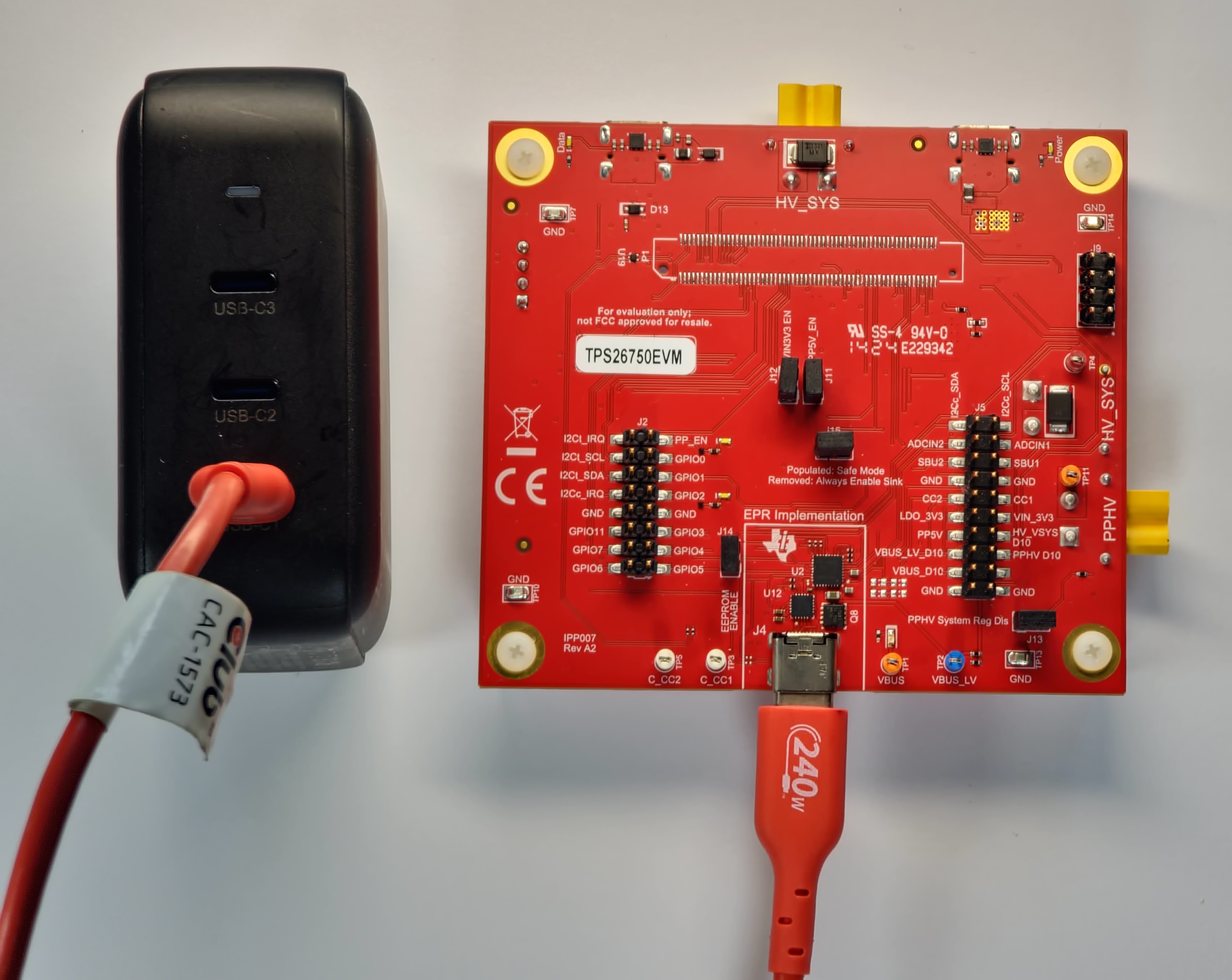
The example setup in Figure 2-6 shows the Aergiatech 140W 3 Port PD3.1 Supported Wall Adapter, whose USB-C1 port is capable of providing 140W (28V at 5A) of power, connected to a USB-C to USB-C 240W capable cable, which is in turn connected to the Power Type C port (J3) of the TPS26750EVM. This example setup is capable of sinking 28V of power (as the wall adapter can provide at maximum 28V; the TPS26750EVM is not limited to 28V) to the DUT Type C port (J4), which is in the USB-PD Extended Power Range.

Figure 2-6 Dead Battery Safe Mode Example Hardware Setup
Dead Battery Always Enable Sink
 Figure 2-7 Dead Battery Always Enable
Sink Block Diagram
Figure 2-7 Dead Battery Always Enable
Sink Block DiagramThe portions of the EVM highlighted in red are powered upon TPS26750 boot up when testing the device in Dead Battery Always Enable Sink Mode, and are shown in Figure 2-7. This mode occurs when the VIN_3V3 pin of the TPS26750 is unpowered (before a USB-C connection is made) and a USB-PD capable source is connected to the DUT Type C (J4) connector, when Jumper J15 is not populated. During Dead Battery Always Enable Sink Mode, the Bidirectional Power Switch (U20) is closed during the period of time that the TPS26750 boots and loads the configuration. In this mode, the TPS26750 can only operate as a sink and can sink between 5V and 48V (both SPR and EPR capable). After the configuration is loaded and the device is finished booting, the Bidirectional Power Switch remains closed (or open) based upon the configuration loaded and the capabilities of the attached source.
The example setup is identical to the setup in Figure 2-6, except that J15 is not populated. This example setup is capable of sinking 28V of power to the DUT Type C port (J4), which is in the USB-PD Extended Power Range.
TPS26750 and BQ25756
 Figure 2-8 TPS26750 and BQ25756 Block
Diagram
Figure 2-8 TPS26750 and BQ25756 Block
DiagramIf users want to support 5V sourcing, then the power supply needs to provide at least 18W of power, due to the following board requirements:
- 5V 3A for PP5V Power Path
- 120mA for VCONN
- 100mA for Board MCU (U22)
If users want to support EPR sourcing (from 5V to 48V), then the power supply needs to provide at least 15V to the HV_SYS net (using either J3, J8. A battery can be connected to J8 for testing as well). However, the exact amount of power users need to provide depends on the expected load drawn by the sink and the highest voltage EPR contract users want to source.
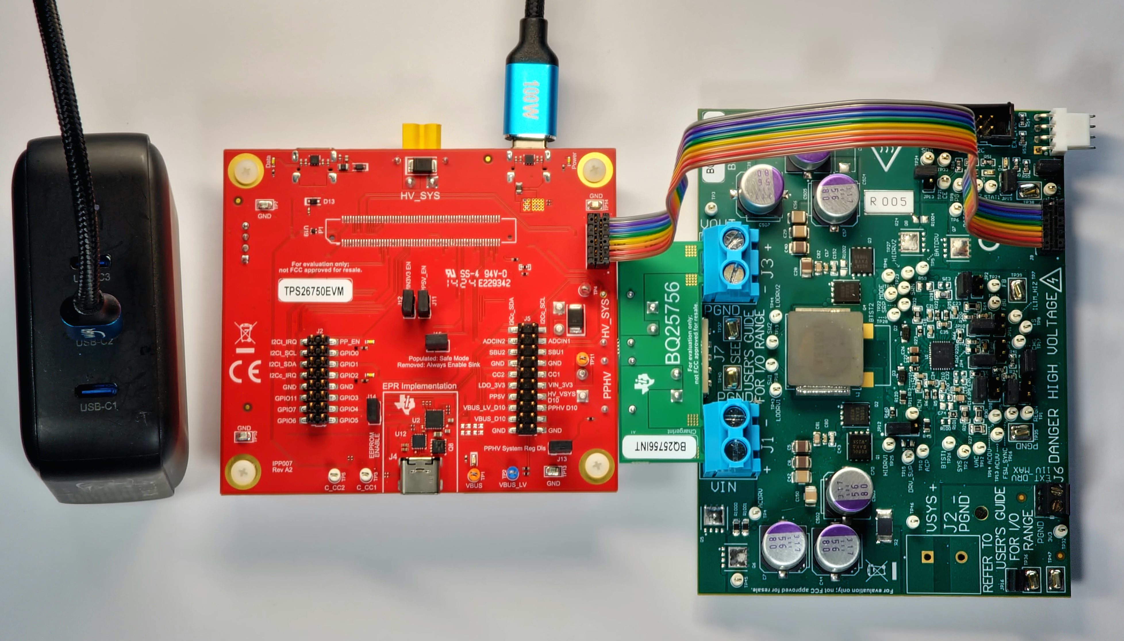
The example setup in Figure 2-9 shows the Aergiatech 140W 3 Port PD3.1 Supported Wall Adapter, whose USB-C2 port is capable of providing 100W (20V at 5A) of power, connected to a USB-C to USB-C 100W capable cable, which is in turn connected to the Power Type C port (J3) of the TPS26750EVM. This example setup is capable of sourcing 48V of power to the DUT Type C port (J4), which is in the USB-PD Extended Power Range.
To source and sink power in the EPR range using the TPS26750EVM, users want connect a simulated battery to the HV_SYS header (J8) instead of powering the board through J3.

Figure 2-9 TPS26750EVM and BQ25756EVM Example Hardware Setup