SLVUCR9B August 2023 – January 2024 TPS2HCS10-Q1
1.3 Specification
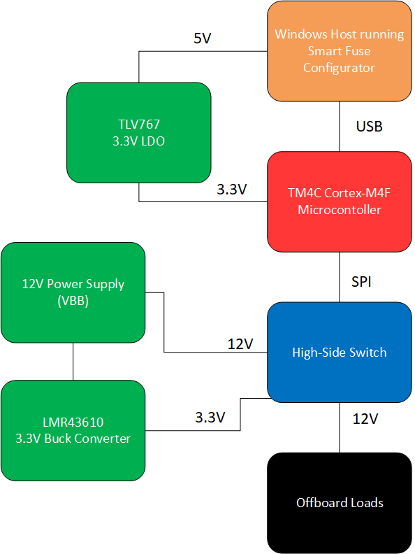
The HSS-HCMOTHERBRDEVM and daughter card boards are meant to be used together to evaluate automotive applications where high-side switches are used to drive primarily off-board loads. This EVM contains a pre-flashed microcontroller with firmware that acts as a SPI<-> USB bridge between the high-side switch (SPI) and the host PC system running the GUI (USB). The EVM is designed for ease-of-use and all that is needed is to plug in USB and relevant loads, supply power, and evaluate through the GUI. A block diagram of the various blocks of the EVM can be seen below.
 Figure 1-1 Block Diagram for
HSS-HCMOTHERBRDEVM
Figure 1-1 Block Diagram for
HSS-HCMOTHERBRDEVMAs seen from the image above, the EVM has multiple power rails that are derived from input power sources. The 12 V supply voltage is fed into a LMR43610 buck converter to derive the 3.3V rail for the high-side switch. This buck converter is used for the low IQ functionality, so that the low-power mode of the high-side switch can be measured through the EVM. A TLV767 LDO is used to derive the 3.3V microcontroller supply from the 5 V USB connection through the PC.
Note that this board is intended to evaluate the standard functionality of the device. The board is not designed to withstand automotive transients events such as hard short-to-ground events, reverse battery events, and ISO 16750-2 load dumps. If short-to-ground is to be performed on the EVM, please refer to the Transient Testing section on how to run transient testing safely on the EVM.