SLVUCR9B August 2023 – January 2024 TPS2HCS10-Q1
3.1.3 Device Settings
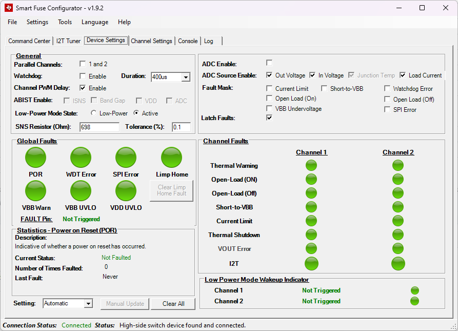
The Device Settings tab allows the user to change device level settings that are not specific to one channel of the device. Additionally in the Device Settings tab, all fault diagnostics are shown as well as statistics and descriptions of each individual faults (both device-wise and channel-wise). A non-faulted example of this view can be seen below.
 Figure 3-11 Device View
From here, the user can click and change any setting in the General box and the corresponding device setting is changed. Additionally, this tab shows the fault diagnostics of the device in real-time. If the Setting box is set to Automatic, then a thread runs in the background that periodically polls the fault status of the device. When faulted, the corresponding fault circle changes red. The user can click any of the circles to populate the Statistics box with a description of the fault and when the last fault occurred and the total number of times that the specific fault triggered.
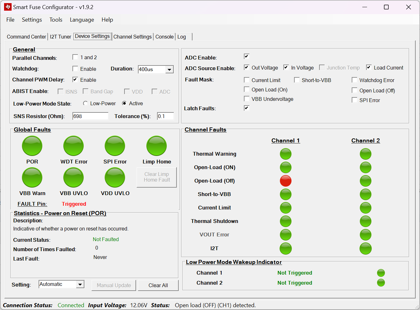
 Figure 3-12 Faulted Device View
In the example above, an open-load fault on channel one is reported. Note that when certain faults occur, the FAULT pin is also reported to be triggered. This pin is the open-drain fault pin that goes from the high-side switch to the microcontroller.
Note that some of the device faults (such as POR) are cleared on read. This makes the device faults not desirable for the GUI to auto-poll the fault status as an important fault event can potentially be missed. To remedy this, the device can be set into Manual update mode. In this mode, the user must click the Manual Update button to read the fault status and update the indications on the GUI.