SLVUCX1 September   2024 TPS548B23


  1.   1
  2.   Description
  3.   Get Started
  4.   Features
  5.   Applications
  6.   6
  7. 1Evaluation Module Overview
    1. 1.1 Introduction
    2. 1.2 Kit Contents
    3. 1.3 Specification
    4. 1.4 Device Information
  8. 2Hardware
    1. 2.1 Configurations and Modifications
      1. 2.1.1 Multifunction Configuration (CFG1-5) Pins Selection
      2. 2.1.2 Setting Output Voltage Using External Feedback Configuration
  9. 3Implementation Results
    1. 3.1 Test Setup and Results
      1. 3.1.1 Input and Output Connections
      2. 3.1.2 Efficiency
      3. 3.1.3 Output Voltage Regulation
      4. 3.1.4 Load Transient and Loop Response
      5. 3.1.5 Output Voltage Ripple
      6. 3.1.6 Start-up and Shutdown with EN
      7. 3.1.7 Thermal Performance
  10. 4Hardware Design Files
    1. 4.1 Schematic
    2. 4.2 Board Layout
      1. 4.2.1 Layout
    3. 4.3 Bill of Materials
  11. 5Additional Information
    1. 5.1 Trademarks

Start-up and Shutdown with EN

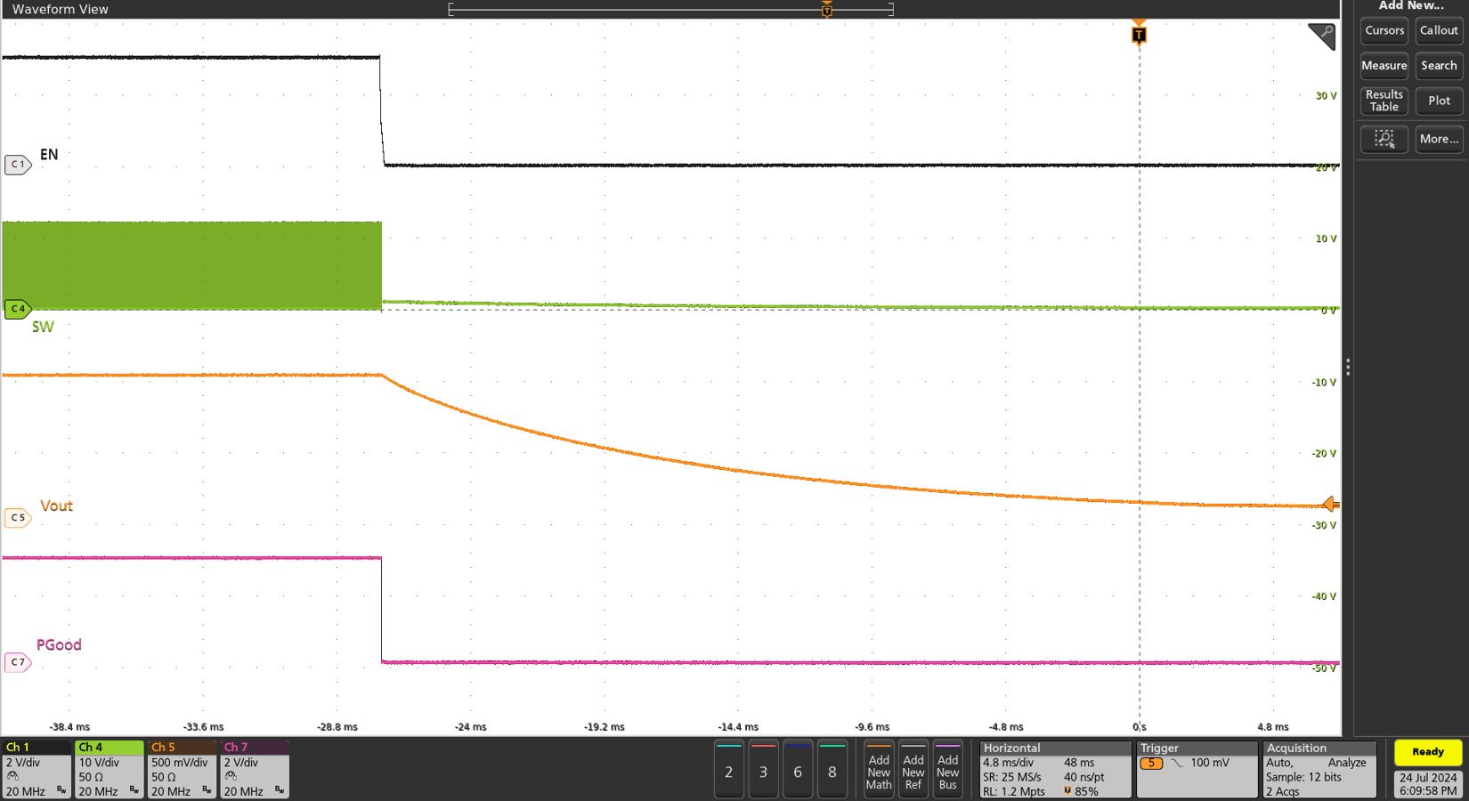
The start-up and shutdown waveforms with EN are shown in Figure 3-11 and Figure 3-12. The input voltage is initially applied and the output is inhibited by pulling EN to GND using an external function generator, as shown in Figure 3-11. When the EN voltage is increased above the enable-threshold voltage, the start-up sequence begins and the output voltage ramps up to the externally set value. The external function generator pulls EN to ground and the TPS548B23 shuts down, as shown in Figure 3-12.
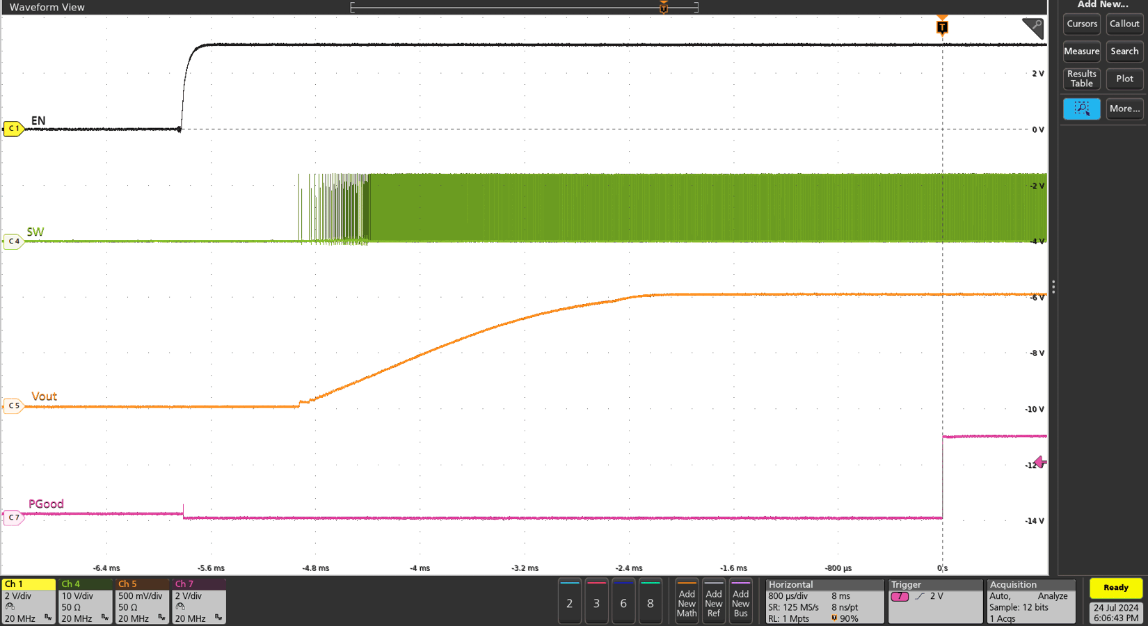
TPS548B23EVM Start-up with
            EN – 20A LoadFigure 3-11 Start-up with EN – 20A Load
TPS548B23EVM Shutdown with EN – 20A LoadFigure 3-12 Shutdown with EN – 20A Load