SLVUCZ9 July   2024 DRV81004-Q1 , DRV81008-Q1 , DRV81602-Q1 , DRV81620-Q1


  1.   1
  2.   Description
  3.   Get Started
  4.   Features
  5.   Applications
  6.   6
  7. 1Evaluation Module Overview
    1. 1.1 Introduction
    2. 1.2 Kit Contents
    3. 1.3 Specification
    4. 1.4 Device Information
  8. 2Hardware
    1. 2.1 Header Information
    2. 2.2 Connector and Jumper Information
    3. 2.3 Hardware Setup
  9. 3Software
    1. 3.1 Software Setup
    2. 3.2 Web GUI Access or Local GUI Installation
    3. 3.3 Connecting EVM to GUI
    4. 3.4 GUI Overview
      1. 3.4.1 Low-Side Drivers: DRV81004-Q1 and DRV81008-Q1
      2. 3.4.2 High-Side Driver: DRV81080-Q1
      3. 3.4.3 Configurable HS/LS: DRV81602-Q1, DRV81242-Q1, and DRV81620-Q1
  10. 4Hardware Design Files
    1. 4.1 Schematics
    2. 4.2 PCB Layouts
    3. 4.3 Bill of Materials (BOM)
  11. 5Additional Information
    1. 5.1 Known Hardware or Software Issues
    2. 5.2 Trademarks

Hardware Setup

The EVM hardware is designed and kitted to simplify setup and begin spinning motors. The EVM comes with the jumpers placed at the appropriate location in the headers. The location of the jumpers, also called shunts, are shown in Section 2.2.

Note: Before using the EVM, check that the shunt location matches the location shown in Section 2.2.

Before connecting the EVM to the GUI software, follow these steps:

  1. Connect EVM to PC via USB connector. D2 (EZFET), D5 (3.3V), must be solid ON.
  2. Connect power supply (less than 40V) to power connector. Make sure terminals are connected correctly to avoid damage due to reverse battery connection.
  3. Turn ON power supply D6 is solid ON.
  4. Connect motor to the appropriate output connector.
  5. Set up is now complete (see Figure 3-8).
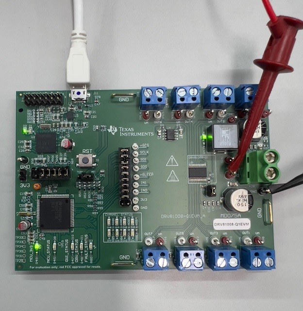
DRV81008-Q1EVM, DRV81602-Q1EVM, DRV81242-Q1EVM,  DRV81008-Q1EVM Hardware
                    Setup Figure 2-8 DRV81008-Q1EVM Hardware Setup