SLVUD01 November 2024 LP5899-Q1
2.2 Setup
LP5899EVM is the connectivity IC between MCU and LP589x Family LED Driver. This section provides the guidance to use LP5899EVM to control LP5891Q1EVM by SPI.
Following the suggested jumper setting, the board can be evaluated by USB power directly and does not need an external power supply. Single LP5891EVM can be quickly set up and tested by following these steps:
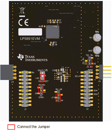
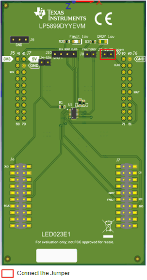
- Following the jumper setting in Figure 2-1 and Figure 2-2 .
-

Figure 2-1 LP5891EVM Jumper Connection Figure 2-2 LP5899EVM Jumper
Connection
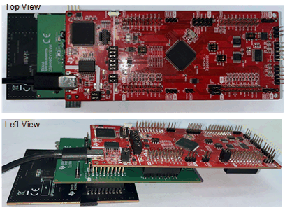
 - Connect the BoosterPack™ connectors (J5, J6, J7, J8) on the LP5899EVM
with the BoosterPack connectors (J1, J2) on the LP5891Q1EVM as shown in the
Figure 2-3.
Figure 2-3 LP5899EVM and LP5891EVM Connection - Connect BoosterPack connectors
(J1, J2, J3, J4) on the LAUNCHXL-F280039C with the BoosterPack connectors (J3,
J4) on the LP5899EVM as shown in the Figure 2-4.

Figure 2-4 LAUNCHXL-F280039C and LP5899EVM Connection - Power the LAUNCHXL-F280039C through the USB cable.
- Download the code into the LAUNCHXL-F280039C with TI Code Composer Studio™ software.
