SLYA051B October 2020 – May 2024 DRV5055 , DRV5055-Q1 , DRV5057 , DRV5057-Q1 , TMAG5170 , TMAG5170-Q1 , TMAG5170D-Q1 , TMAG5173-Q1 , TMAG5273
2 Linear Transit Position Sensing
When the transit of a magnet is being monitored, we can determine position most accurately using linear Hall sensors. Total observable range for a single sensor is maximized by orienting the magnet as shown in DRV5055 Magnet Orientation for Linear Stroke Detection and by using a bipolar linear Hall Effect sensor which is capable of detecting both North and South poles of the magnet.
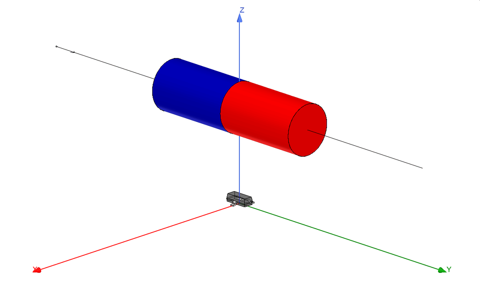 Figure 2-1 DRV5055 Magnet Orientation for
Linear Stroke Detection
Figure 2-1 DRV5055 Magnet Orientation for
Linear Stroke DetectionIn the example shown in DRV5055 Magnet Orientation for Linear Stroke Detection , we have a N42 type Neodymium magnet traveling along a 60 mm path parallel to the y-axis. The center of the magnet is separated from the sensor by an air gap of 8 mm. The magnet has a diameter of 6.3 mm (0.25 in) and a length of 22.2 mm (0.875 in). Observed DRV5055 Magnetic Flux Density shows the expected input that DRV5055 would experience during the transit of the magnet. Here we see that the maximum z-component detected by the sensor is about 24.9 mT.
 Figure 2-2 Observed DRV5055 Magnetic Flux
Density
 A linear Hall sensor such as DRV5055 works well in this application. For this device there are four sensitivity ranges available:
|
Package Variant |
Sensitivity (Vcc = 5 V) |
Sensitivity (Vcc= 3.3 V) |
|---|---|---|
|
A1 |
100 mV/mT |
60 mV/mT |
|
A2 |
50 mV/mT |
30 mV/mT |
|
A3 |
25 mV/mT |
15 mV/mT |
|
A4 |
12.5 mV/mT |
7.5 mV/mT |
When selecting the best sensor for the application we want to utilize as much of the linear output swing of the device as possible. In every case, 0 mT input produces an output at Vcc/2. For this example, select A1 at a sensitivity of 60 mV/mT, which generates a maximum output swing of ±1.49 V.
The peak field observed by the sensor can be adjusted by a number of factors:
| Magnet Variation | Peak B-Field | Detection Range | Other Effects |
|---|---|---|---|
|
Air Gap |
Reducing the air gap between the magnet and sensor results in an increase in peak B-Field. | Decreases in Air Gap produce minor increases to detection range, primarily in the non-linear region of the input. |
As the air gap is reduced, a non-linear region becomes more pronounced across magnet transit. |
|
Magnet Length |
An increase to magnet size results in an increase in peak B-Field. |
Magnet length is the governing factor in determining the detectable range for the sensor. |
Physically larger magnets costs more to use in production. |
|
Magnet Radius |
An increase to magnet size results in an increase in peak B-Field. |
Increases to magnet radius produce minor increases to detection range, primarily in the non-linear region of the input. |
Physically larger magnets costs more to use in production. |
|
Magnet Material |
Increasing the strength of the magnetic material likewise causes an increase in peak observed B-Field |
Stronger magnetic materials produce minor increases to detection range, primarily in the non-linear region of the input. |
Stronger magnetic materials costs more to use in production |
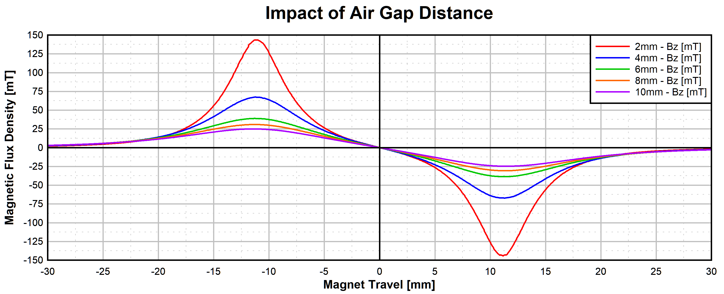 Figure 2-3 Impact of Magnet Variables
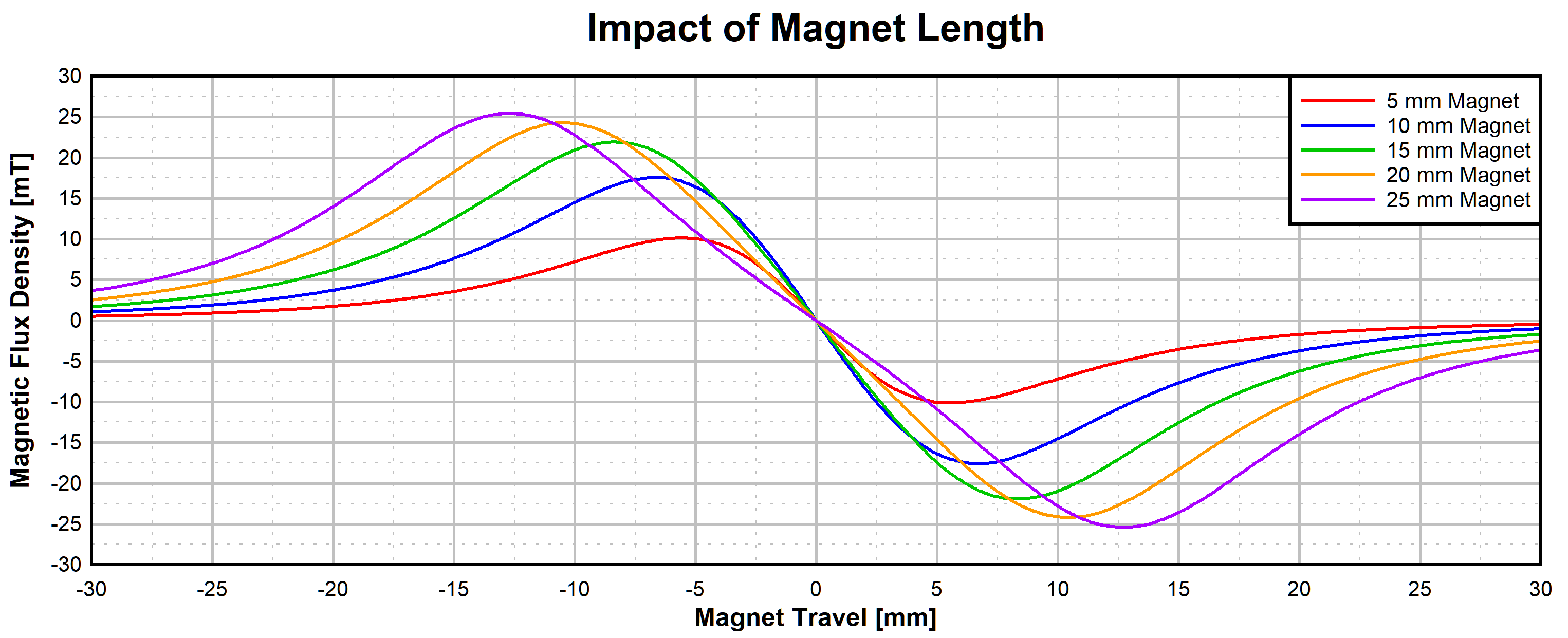 Figure 2-4 Impact of Magnet Length
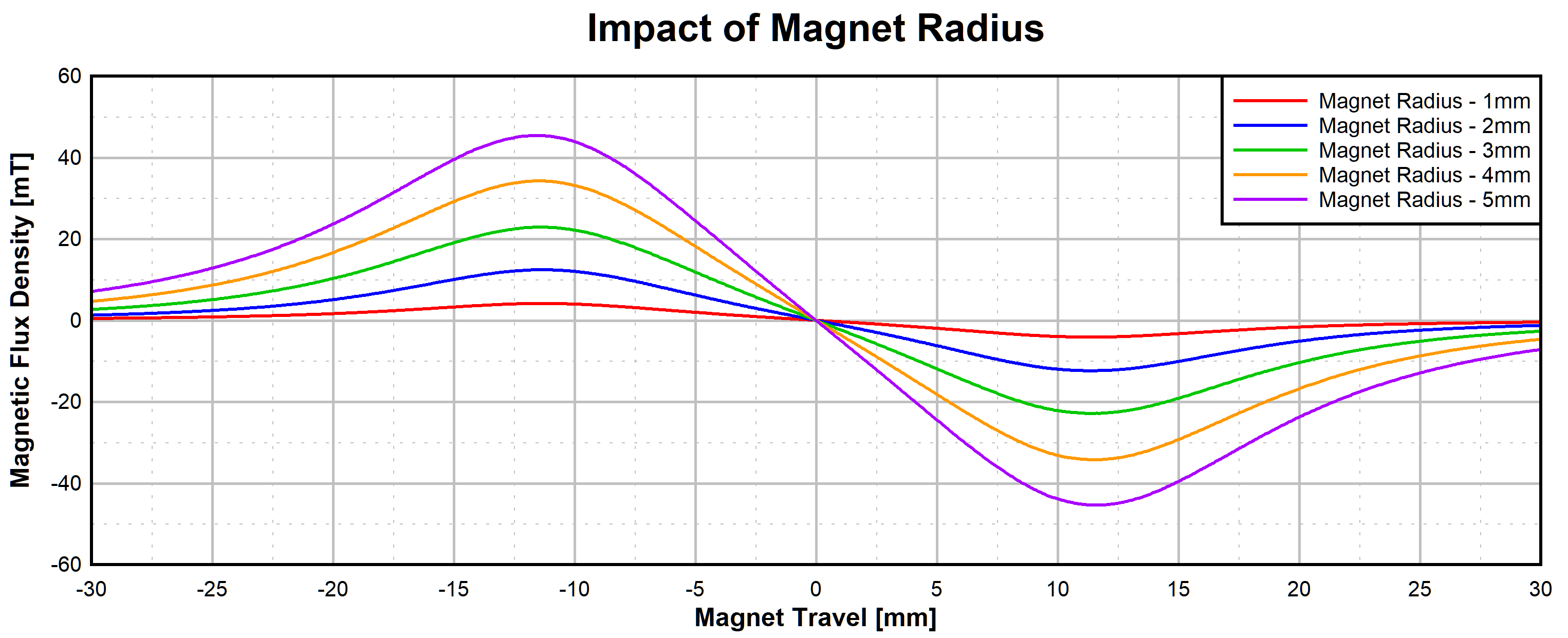 Figure 2-5 Impact of Magnet Radius
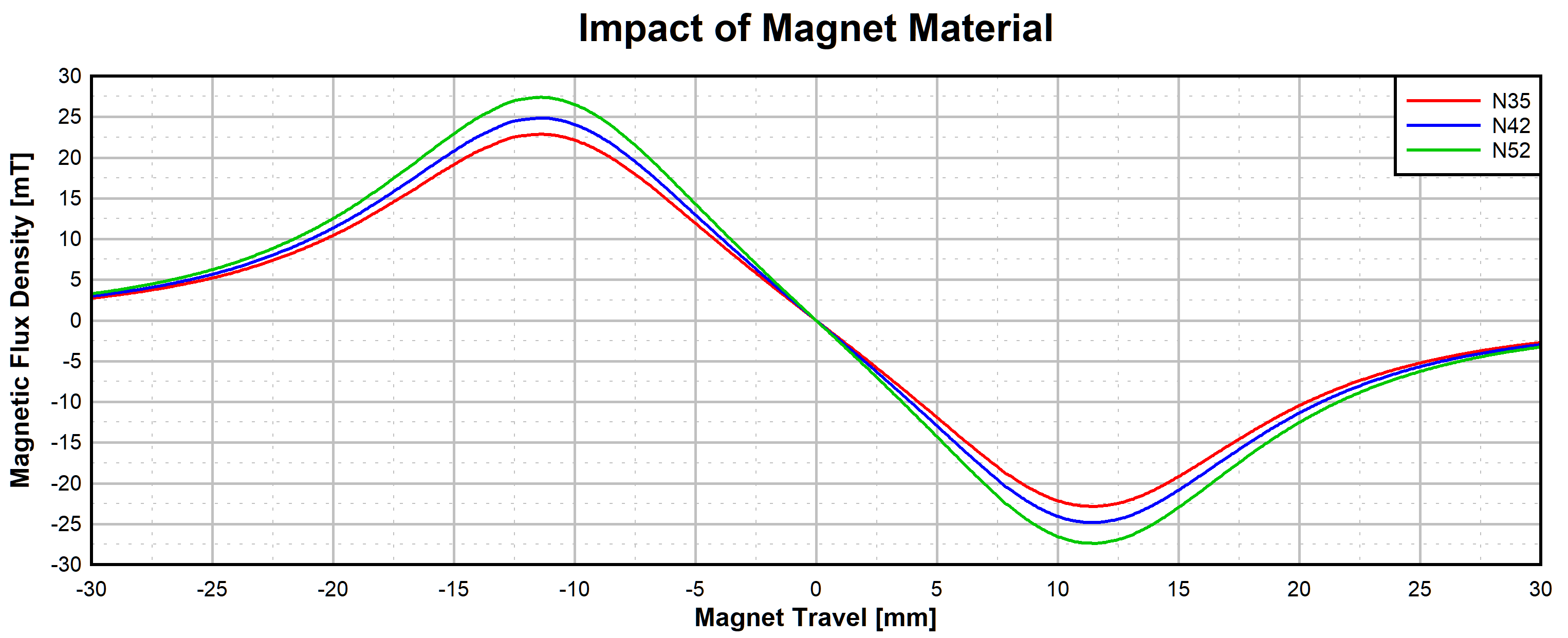 Figure 2-6 Impact of Magnet Material
Reviewing Observed DRV5055 Magnetic Flux Density shows that for each value of Bz,there are two possible magnet positions. To resolve ambiguity, measurements should be based solely on the region of the plot immediately between the maximum and minimum values. Excluding the portion nearest the extremes, this part of the output response is typically very linear.
This means that for the total travel distance in this example we can distinguish positions ranging from about ±10 mm. Notice that this range from peak to peak is approximately the length of the magnet, 22 mm.
In fact, the B-Field produced by the magnet in this orientation is governed by the length of the magnet. Thus, to expand the range of a single sensor it is necessary to increase the length of the magnet. Using stronger magnetic materials may add minute increases to the total range, but this is mainly only effective to increase the available air gap between the sensor and the magnet.
Cost can often be a limiting factor for implementing solutions with long magnets. If the range of a single magnet/sensor combination is inadequate, then the most practical approach is to expand the design by using additional sensors in a linear array.