SLYA051B October 2020 – May 2024 DRV5055 , DRV5055-Q1 , DRV5057 , DRV5057-Q1 , TMAG5170 , TMAG5170-Q1 , TMAG5170D-Q1 , TMAG5173-Q1 , TMAG5273
4 Absolute Rotational Position
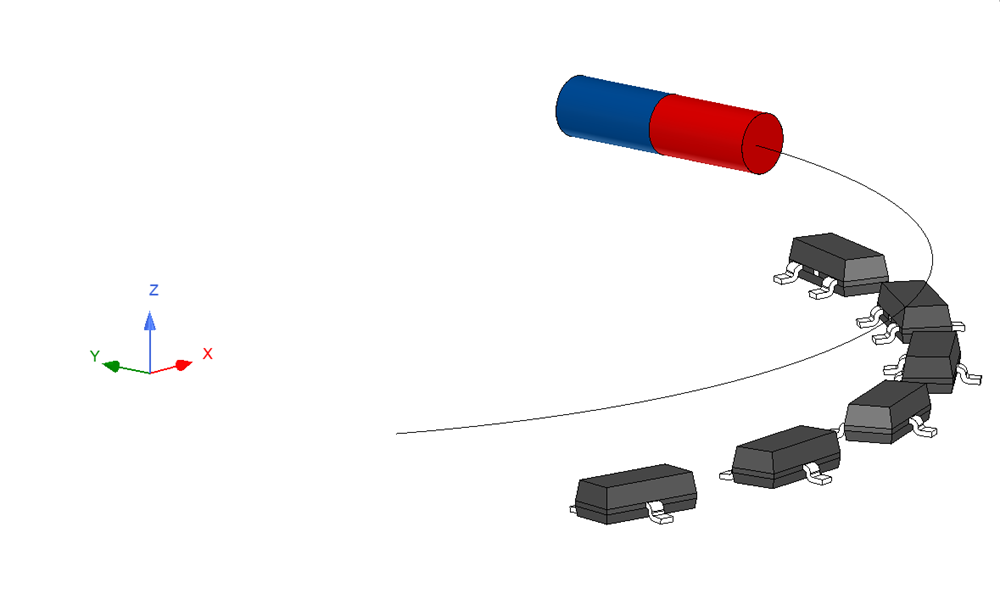
This same linear arrangement for this application may be transformed into a rotational measurement as well. For example, now consider a cylindrical magnet with a radius of 1/32” and a thickness of ¼” made of N52 material. The magnet is placed such that there is approximately a 2-mm gap between the magnet and sensor. The magnet rotates about the z axis at 20 mm from center. Again, the selected sensor is DRV5055A1 with a sensitivity of 60 mV/mT.
 Figure 4-1 DRV5055 Circular Array
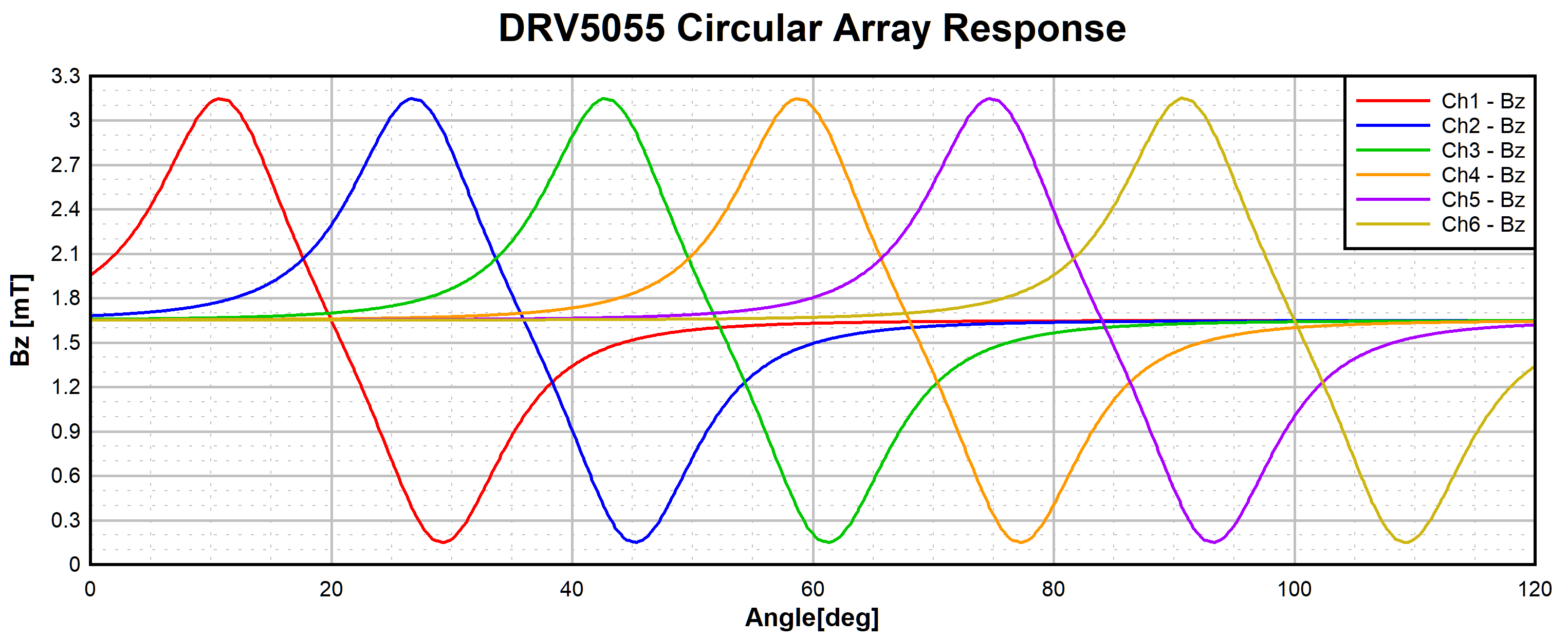
In this scenario we find a spacing of about 16° from sensor to sensor provides a continuous gradient output. With six sensors in this format we are able to accurately monitor about 99° (10° to 109°) .
 Figure 4-2 DRV5055 Circular Array
Output
Figure 4-2 DRV5055 Circular Array
OutputWith this implementation of the linear Hall sensor array, we are now able to track movement along a circumference. Typically angle calculations can be done with 2 sensors installed adjacent to a rotating cylindrical magnet. A rotational array configuration allows for flexibility of magnet placement and is useful in cases where it is not practical to place a magnet or sensors on or near the axis of rotation.