SLYU063 September 2024 TMAG5233
2 Hardware
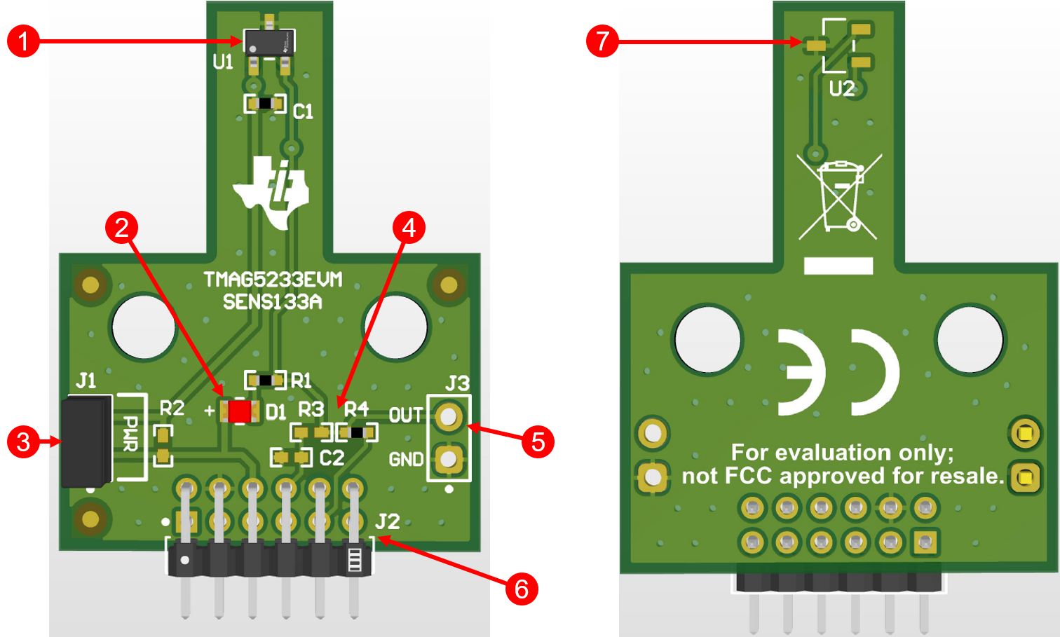
The EVM is an easy-to-use platform for evaluating the main features and performance of the TMAG5233. The EVM provides LEDs tied to the outputs of the device for easy evaluation of the switch and a jumper in-line with the power supply to measure the device current or provide an external power supply. Users can also monitor the output through a test point on the right side of the board or through the header pins at the bottom of the board. All of these features allow the EVM to operate as a stand-alone board without the need of an MCU to process the digital output.
 Figure 2-1 TMAG5233EVM With Callouts.
 | CALLOUT NUMBER | DESCRIPTION |
|---|---|
|
1 |
TMAG5233 |
|
2 |
LED connected to TMAG5233 OUT pin |
|
3 |
Power header to measure current or provide external power |
|
4 |
Resisters to connect/disconnect to J2 |
|
5 |
Connection points for OUT pins and GND |
|
6 |
SCB connector |
|
7 |
Alternate placement for TMAG5233 (rotated 90°) |
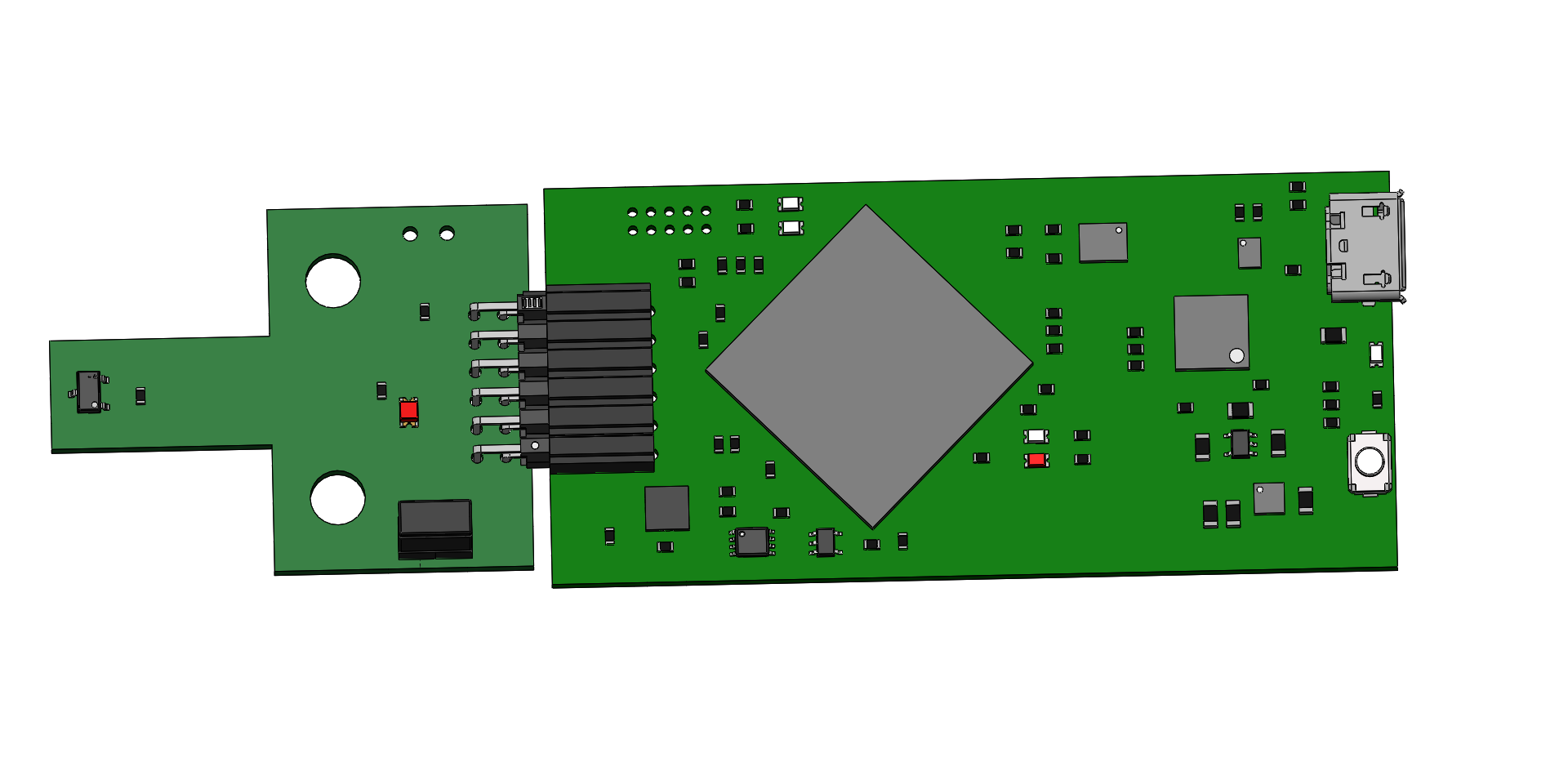
Alternatively, the bottom headers are compatible with the TI-SCB, which can power the EVM and read the digital output using a GPIO pin. Figure 2-2 shows how to connect the EVM to the SCB.
 Figure 2-2 EVM Connected to SCB
The EVM is intended to provide basic functional evaluation of the device. The layout is not intended to be a model for the target circuit, nor is the EVM laid out for electromagnetic compatibility (EMC) testing.