SLYY081B March 2018 – January 2024 AMC1305M25 , AMC1311 , AMC1311-Q1 , ISO1042 , ISO1042-Q1 , ISO5851 , ISO7741 , ISO7841 , ISOM8710 , UCC20225-Q1 , UCC20225A-Q1 , UCC21520 , UCC21540 , UCC23513 , UCC5390
Failure mode 1: High voltage across the isolation barrier
An example of an isolator configuration is shown in Figure 2. The isolator has two sets of pins. One set is on side 1 and the other set is on side 2. In normal operation, the pins on side 1 are all low voltage with respect to GND1; and the pins on side 2 are all low voltage with respect to GND2. The power dissipated in the isolator depends on voltages and currents applied to the isolator’s pins. In normal operation, power is maintained below the maximum limits specified in the isolator’s data sheet. Very high voltage can exist between GND1 and GND2.This voltage appears across the isolator’s internal isolation barrier.
 Figure 2 Example normal operating configuration of an isolator.
Isolators are designed to withstand high voltage transient profiles of different magnitude and duration. Correspondingly, the isolation performance of the isolator is quantified by several parameters. The 60-second isolation withstand voltage (VISO and VIOTM) indicates tolerance to short duration overvoltage caused on the system supply lines by switching loads or faults. Repetitive peak or working voltage (VIOWM and VIORM) is the voltage that the isolator can withstand on a continuous basis throughout its operating lifetime. Surge withstand voltage (VIOSM) represents tolerance to a particular transient profile (1.2/50 μs – see IEC 61000-4-5) that represents voltages induced on the power supply lines during direct and indirect lightning strikes.
For each parameter, the limit is set by the voltage value that causes the isolation barrier to break, creating a short circuit from one side of the isolator to another. These parameters are indicated in the isolator’s datasheet and reflect the ability of the isolator to handle high voltage without damage. A detailed discussion of these parameters is presented in reference [1]. At the system level, for example for the motor drive system shown in Figure 1, the incoming supply lines do experience the different over-voltage profiles mentioned above. With one end of the isolated gate-driver galvanically connected to the AC lines, and the other end referenced to earth, it is clear that the isolation barrier in the gate-driver directly faces these stresses.
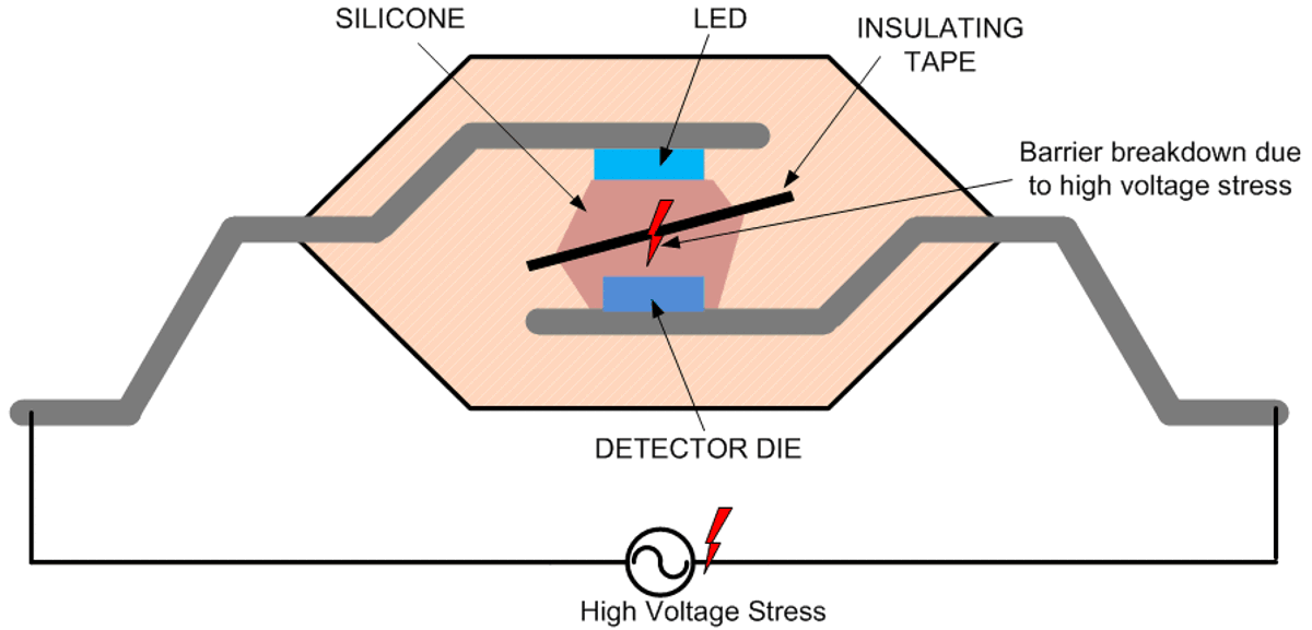
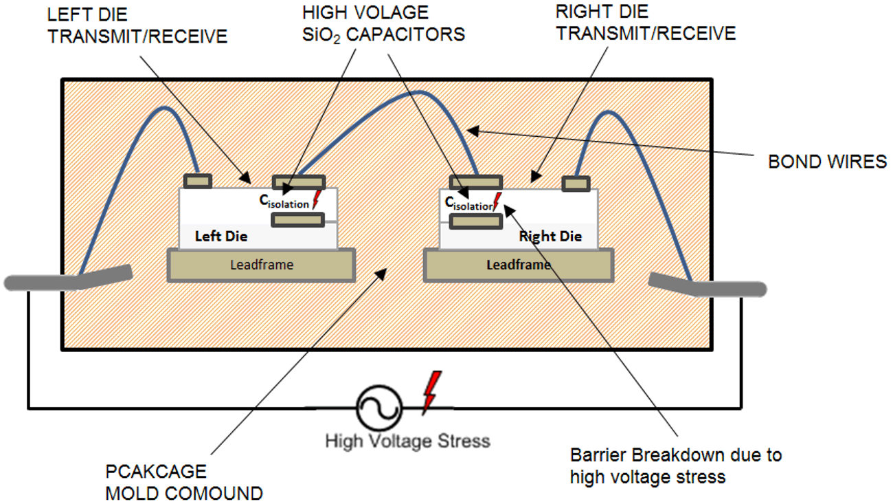
Figure 3 and Figure 4 depicts these high-voltage stresses appearing across the isolation barrier, for example, using an optocoupler and a series capacitor reinforced isolator from TI. As the stress voltage increases beyond the isolators’ safety limiting values, the isolation barrier can degrade, creating a low resistance path between sides 1 and 2. In the case of optocouplers, the isolation barrier is a combination of silicone and insulating tape; whereas in the case of isolators from TI, it is a series combination of two high voltage SiO2 capacitors. In each case, since the rated limits are obtained by failing the isolation barrier, by definition, both isolators “fail short.”
 Figure 3 High-voltage stress across an optocoupler.
 Figure 4 High-voltage stress on a series-capacitor isolator.
Depending on the application, end-equipment standards determine the specifications for isolators being used in the system. These standards ensure that isolators are stronger than the voltage stress levels they are likely to encounter across the isolation barrier in a realistic use case. For example, the IEC 61800-5-1 sets the requirements for isolators used in AC motor drive applications. Choosing an isolator that complies with the end-equipment standard minimizes the risk of breakdown of the isolation barrier through overvoltage during actual operation. However, if the isolator exceeds standard requirements, the risk can be reduced further.
Reinforced isolation devices from TI described in this paper use SiO2 as the insulation material, which has a much higher breakdown strength (500 V/μm) than those used by competing solutions. For example, silicone and mold compound used in traditional optocouplers have breakdown strengths of 30 V/μm to 50 V/μm. TI reinforced isolators are also built using a precision semiconductor fabrication process, leading to a tight control on dimensions and spacing. Due to these two factors, TI devices have very high isolation performance for a given package. They effectively address temporary over voltages and surges as well as continuous high-voltage operation for many years. For example, TI Isolators in 16-SOIC packages have 50 percent higher working voltage than similar competing solutions. Further details regarding isolation performance of TI isolators can be found in the corresponding product data sheets, and in reference [1].
For a given application, TI reinforced isolation devices can provide crucial margin, even beyond the requirements mandated by the end equipment standards, which minimizes the likelihood of failure mode 1. A discussion of the IEC 61800-5-1 standard and a performance comparison of TI isolators against the requirements of this standard are provided in reference [2].