SLYY217 September 2022 AM2631 , AM2631-Q1 , AM2632 , AM2632-Q1 , AM2634 , AM2634-Q1 , UCC14130-Q1 , UCC14131-Q1 , UCC14140-Q1 , UCC14141-Q1 , UCC14240-Q1 , UCC14241-Q1 , UCC14340-Q1 , UCC14341-Q1 , UCC15240-Q1 , UCC15241-Q1 , UCC5870-Q1 , UCC5871-Q1 , UCC5880-Q1
Driving efficiency with fast current-sensing feedback loops and high-speed controllers
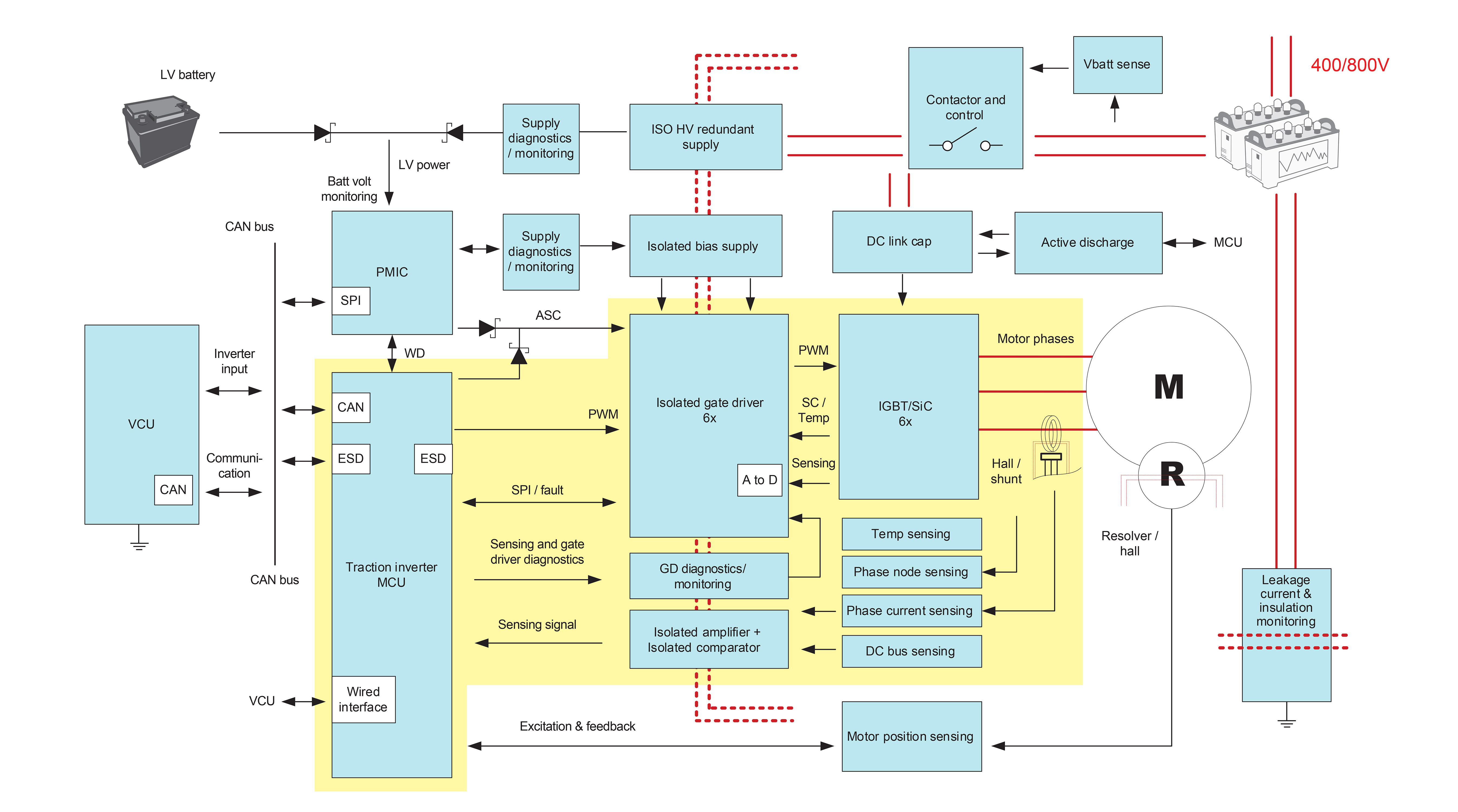
One way to improve the EV driving experience, which includes steady cruise control, responsive acceleration and deceleration, and a quieter cabin experience, is to improve the overall accuracy and reliability of the current-sensing feedback loop. This control loop is the pathway that the sensed currents take from the output of the traction inverter’s phases, back through isolated precision amplifiers and through the microcontroller (MCU) for processing. This journey finally results in the signals that come back to the control output of the traction inverter. Optimizing the motor-control loop enables fast and precise feedback so that the motor can react quickly to changes in speed or torque. The highlighted portion in Figure 1 shows the motor-control loop.
 Figure 1 Traction inverter block
diagram, with the motor-control loop and power stage highlighted in
yellow.
Figure 1 Traction inverter block
diagram, with the motor-control loop and power stage highlighted in
yellow.As detailed in Figure 2, isolated semiconductor components typically isolate the power and control circuits in a traction inverter. Three isolated amplifiers or modulators measure motor currents through a shunt resistor and feed the signals to an MCU’s algorithm for field-oriented control (FOC). The need to increase motor speeds requires a higher-bandwidth current-sensing feedback loop, which means that the in-phase current must generate a modified inverter output as quickly as possible. The latency of the current-sensing feedback loop is a priority, especially because power transistor switching frequencies (the insulated gate bipolar transistors [IGBTs]/SiC MOSFETs in Figure 1) are increasing to tens of kilohertz, and control signals must change the pulse width, cycle by cycle, in order to enable a high rotational speed. Noise generated by high currents also affects loop reliability.
Given that the isolated amplifiers are positioned right next to the source of noise, it is important that they operate reliably, with minimal noise interference between the power and control circuits. This is why galvanically isolated amplifiers that offer high transient noise immunity between the power ground and signal ground are necessary in the current-sensing loop. With proper component selection, an accurate current-sensing loop can limit the harmonic distortion of the three current phases to support smooth motor speed and torque control during acceleration and braking conditions. The accuracy of the current-sensing loop also helps prevent electrical losses and minimizes vibrations while driving. Isolated amplifiers such as the AMC1300B-Q1 and AMC1311B-Q1 and isolated modulators such as the AMC1306M25 and AMC1336 support accurate current and voltage measurements with over 200 kHz of bandwidth along with latency of less than 2 µs and galvanic isolation with common-mode transient immunity (CMTI) over 100 kV/µs.
The MCU must take the given three-phase current measurements through an analog-to-digital converter (ADC) to quickly digitize the measurements and feed through the main algorithm to generate pulse-width modulation (PWM) for the traction inverter’s output. The FOC algorithm often used in motor-control designs requires complex math, such as fast Fourier transform (FFT) and trigonometric operations. This leads to high processing bandwidth requirements, especially for switching frequencies of 20 kHz and more.
It is important to distribute the power loads of the MCU so that it can handle both the motor control and safety functions for the traction inverter. A high-speed FOC implementation enables more headroom to the power and processing capability within the MCU to process both motor control and functional safety features. Real-time MCUs such as the C2000™ TMS320F28377D, TMS320F28386D, TMS320F280039C and Sitara™ AM2634-Q1 effectively provide fast control-loop performance, with help from a >3-MSPS ADC for sensing and processing power from multiple optimized cores to perform complex control math quickly. Tightly integrated high-resolution PWMs for actuation help generate precise duty cycles for optimized motor control. When optimized for traction inverters, these stages (ADC input, FOC algorithm execution and PWM write) combine to achieve <4-µs control-loop latency.