SLYY221 November 2023 ADC12DJ5200RF , ADS124S08 , ADS127L11 , AFE2256 , REF35 , REF70 , TPS62912 , TPS62913 , TPS7A94 , TPSM82912 , TPSM82913 , UCC5880-Q1 , UCC5881-Q1
- 1
- Overview
- At a glance
- Why high voltage?
- Optimizing wide-bandgap FET performance with component innovations
- Selecting the right gate drivers
- Selecting the right controllers
- Maximizing power density with topology innovations
- Achieving extreme efficiency targets with system-level innovation
- Addressing EMI challenges
- Conclusion
- Additional resources
Achieving extreme efficiency targets with system-level innovation
Today’s component and topology innovations enable power-conversion systems with much higher efficiency than ever before. An emerging DC grid system offers a much simpler, more efficient and more reliable high-voltage solution over traditional centralized AC grid systems. For example, a photovoltaic (PV) power system requires only one power-conversion stage from the PV panels to 120-V or 240-V AC grids. A distributed DC grid system could greatly simplify high-voltage power conversion and increase system availability and reliability.
Beyond system architecture innovations, control system innovations are another way to simplify and improve high voltage power-conversion systems. Let’s continue using PFC as an example. In high-power applications involving AC, a CCM PFC should be the first choice because it allows a lower inductor ripple current; therefore, you will need a smaller differential electromagnetic interference (EMI) filter. Compared to a CCM PFC, a critical-conduction-mode (CRM) PFC has its PFC inductor current always start from zero or even negative with a smaller inductance, which enables much lower switching losses and higher efficiency, as the current of the power switches at the turnon instant is almost zero. The inductor current ripple will be much higher than a CCM PFC when delivering the same power, however, which can make EMI filter design difficult.
A third option offering the right balance between efficiency and differential EMI noise levels is multimode operation – a combination of CCM and CRM operations in every AC cycle. In multimode operation, the PFC inductor inductance should be smaller than the PFC inductor used in CCM operation but larger than the PFC inductor used in CRM operation in order to allow the PFC to have both CCM and CRM operation over an AC cycle. Figure 11 illustrates the ripple current envelopes in these three modes.
 Figure 11 PFC inductor currents (from
left to right) under CCM, CRM and multimode operations.
Figure 11 PFC inductor currents (from
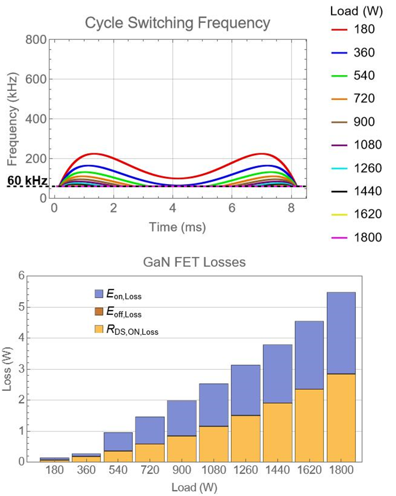
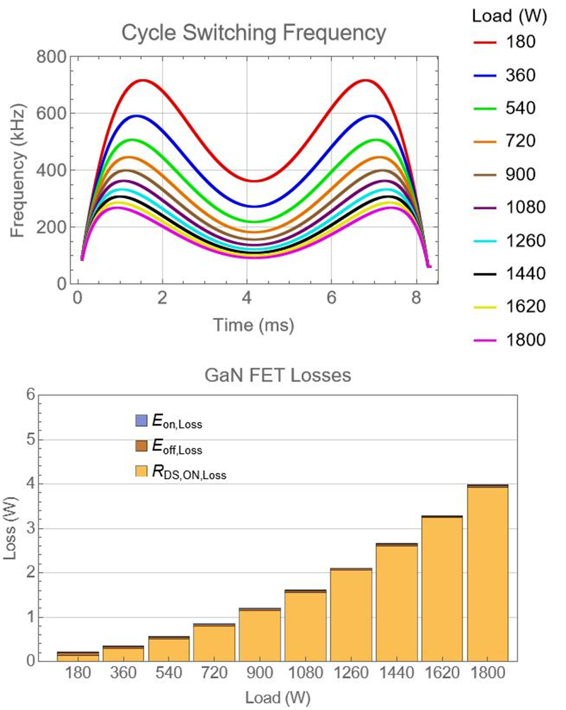
left to right) under CCM, CRM and multimode operations.Figure 12 shows a loss comparison between a multimode PFC and a CRM PFC (assuming that zero voltage switching is guaranteed) with the same specification. The multimode PFC design has a 150-µH PFC inductor with an operational frequency ranging from 60 kHz to 250 kHz, while the CRM PFC design has a 25-µH PFC inductor with an operational frequency ranging from 75 kHz to 750 kHz. As a result, the CRM PFC reduces FET losses over 40% at a half load, with a higher operational frequency and a smaller inductor. This is an indication of where highly efficient high-voltage power-conversion systems should move – toward adopting soft-switching topologies.

 Figure 12 Frequency spectrum and FET
losses in a multimode PFC (left) and a CRM PFC in a 1.8-kW power-supply
unit.