SNAA311A September 2017 – September 2020 LMK00301 , LMK00308 , LMK03328 , LMK04803 , LMK04832 , LMK1C1104 , LMK61E2
2 Clock Tree
Example: Clock tree for 192-channel ultrasound cart-based system.
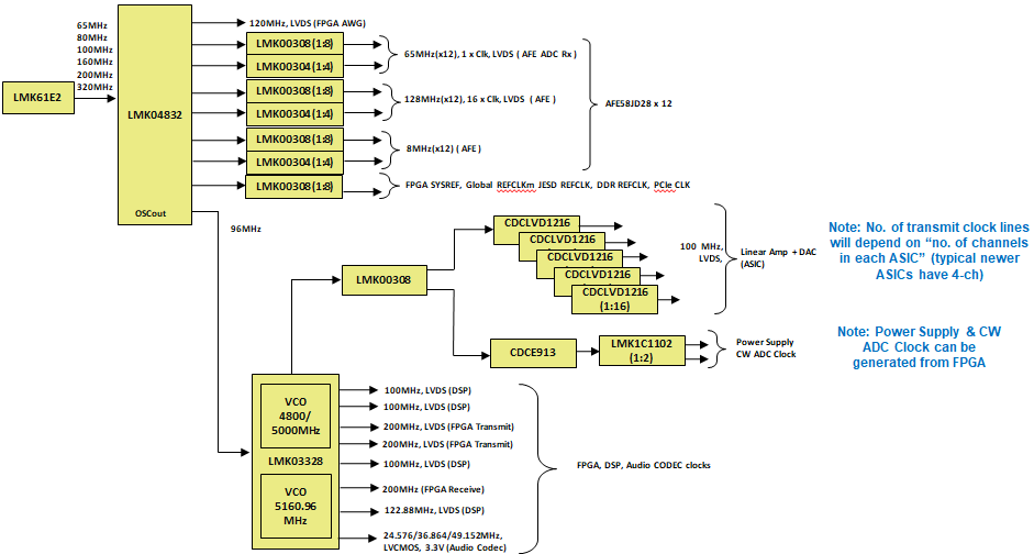 Figure 2-1 Front-End Unit and Back-End
Unit
Figure 2-1 Front-End Unit and Back-End
UnitTests were conducted to demonstrate the total additive jitter and also jitter in various clock configurations for the clock tree by using individual evaluation modules from the different clocking components.
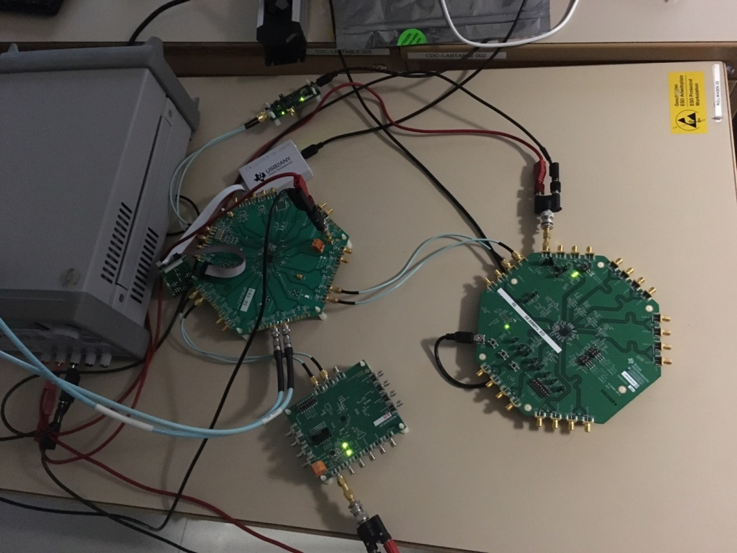 Figure 2-2 Different Clocking Components
The following graphs demonstrate the noise performance of the actual signals as measured on a signal source analyzer.
Demonstration 1:
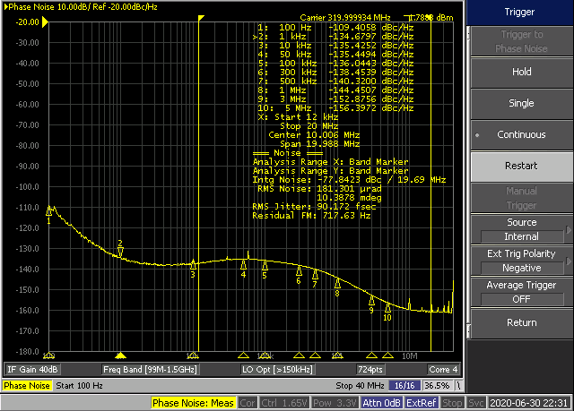
| Reference = 320 MHz LVPECL | ||||
| Integrated RMS Jitter (12 kHz-20 MHz) - 90 fs |
Demonstration 2:
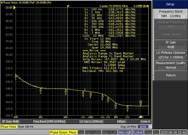
| Reference = 320 MHz from LMK61E2 and LMK04832 output = 80 MHz LVPECL | ||||
| Integrated RMS Jitter (12 kHz-20MHz) - 112 fs |
Demonstration 3:
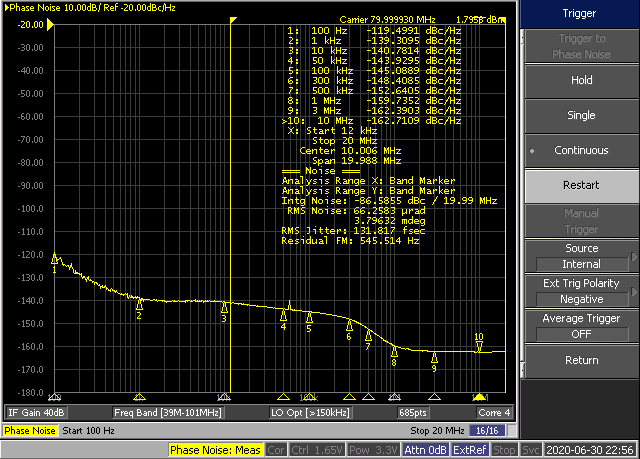
| Input = 80 MHz from LMK04832 and output = 80 MHz LVPECL | ||||
| Integrated RMS Jitter (12 kHz-20 MHz) - 132 fs |
A summary of the three demonstrations follows:
- The total integrated RMS jitter for the LMK61E2 and LMK04832 is 116 fs (RMS). The LMK0030X adds just 70 fs (RMS) to the output of LMK04832.
- The total integrated RMS jitter from LMK61E2 to the output of LMK0030X is just 132 fs.
This clock tree jitter is root-mean square added to the ADC aperture jitter and compared against the jitter requirement derived from the SNR of the ADC to make sure that the clock tree is not degrading ADC performance.
Since the total integrated RMS jitter of the clock tree presented here is low, therefore it will not limit the ADC performance in most ultrasound applications.
 Figure 2-6 Comparison of LMK61E2 to LMK0030X
Figure 2-7 illustrates the PN of various clock devices.
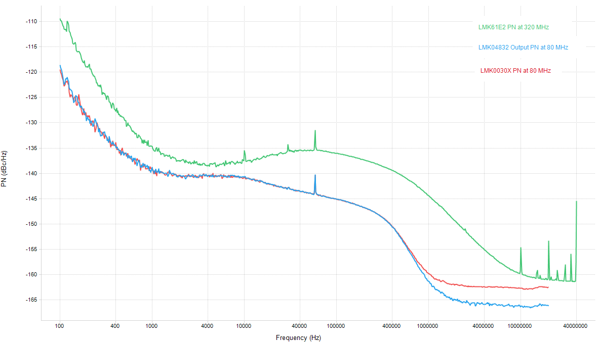 Figure 2-7 PN for Various Clock Devices Normalized to 1 GHz.