SNAS669E September 2015 – April 2018 LMK03318
PRODUCTION DATA.
- 1 Features
- 2 Applications
- 3 Description
- 4 Revision History
- 5 Description (continued)
- 6 Device Comparison Table
- 7 Pin Configuration and Functions
-
8 Specifications
- 8.1 Absolute Maximum Ratings
- 8.2 ESD Ratings
- 8.3 Recommended Operating Conditions
- 8.4 Thermal Information
- 8.5 Thermal Information
- 8.6 Electrical Characteristics - Power Supply
- 8.7 Pullable Crystal Characteristics (SECREF_P, SECREF_N)
- 8.8 Non-Pullable Crystal Characteristics (SECREF_P, SECREF_N)
- 8.9 Clock Input Characteristics (PRIREF_P/PRIREF_N, SECREF_P/SECREF_N)
- 8.10 VCO Characteristics
- 8.11 PLL Characteristics
- 8.12 1.8-V LVCMOS Output Characteristics (OUT[7:0])
- 8.13 LVCMOS Output Characteristics (STATUS[1:0])
- 8.14 Open-Drain Output Characteristics (STATUS[1:0])
- 8.15 AC-LVPECL Output Characteristics
- 8.16 AC-LVDS Output Characteristics
- 8.17 AC-CML Output Characteristics
- 8.18 HCSL Output Characteristics
- 8.19 Power-On Reset Characteristics
- 8.20 2-Level Logic Input Characteristics (HW_SW_CTRL, PDN, GPIO[5:0])
- 8.21 3-Level Logic Input Characteristics (REFSEL, GPIO[3:1])
- 8.22 Analog Input Characteristics (GPIO[5])
- 8.23 I2C-Compatible Interface Characteristics (SDA, SCL)
- 8.24 Typical 156.25-MHz Closed-Loop Output Phase Noise Characteristics
- 8.25 Typical 161.1328125-MHz Closed-Loop Output Phase Noise Characteristics
- 8.26 Closed-Loop Output Jitter Characteristics
- 8.27 PCIe Clock Output Jitter
- 8.28 Typical Power Supply Noise Rejection Characteristics
- 8.29 Typical Power-Supply Noise Rejection Characteristics
- 8.30 Typical Closed-Loop Output Spur Characteristics
- 8.31 Typical Characteristics
- 9 Parameter Measurement Information
-
10Detailed Description
- 10.1 Overview
- 10.2 Functional Block Diagram
- 10.3 Feature Description
- 10.4
Device Functional Modes
- 10.4.1 Smart Input MUX
- 10.4.2 Universal Input Buffer (PRI_REF, SEC_REF)
- 10.4.3 Crystal Input Interface (SEC_REF)
- 10.4.4 Reference Doubler
- 10.4.5 Reference Divider (R)
- 10.4.6 Input Divider (M)
- 10.4.7 Feedback Divider (N)
- 10.4.8 Phase Frequency Detector (PFD)
- 10.4.9 Charge Pump
- 10.4.10 Loop Filter
- 10.4.11 VCO Calibration
- 10.4.12 Fractional Circuitry
- 10.4.13 Post Divider
- 10.4.14 High-Speed Output MUX
- 10.4.15 High-Speed Output Divider
- 10.4.16 High-Speed Clock Outputs
- 10.4.17 Output Synchronization
- 10.4.18 Status Outputs
- 10.5 Programming
- 10.6
Register Maps
- 10.6.1 VNDRID_BY1 Register; R0
- 10.6.2 VNDRID_BY0 Register; R1
- 10.6.3 PRODID Register; R2
- 10.6.4 REVID Register; R3
- 10.6.5 PARTID Register; R4
- 10.6.6 PINMODE_SW Register; R8
- 10.6.7 PINMODE_HW Register; R9
- 10.6.8 SLAVEADR Register; R10
- 10.6.9 EEREV Register; R11
- 10.6.10 DEV_CTL Register; R12
- 10.6.11 INT_LIVE Register; R13
- 10.6.12 INT_MASK Register; R14
- 10.6.13 INT_FLAG_POL Register; R15
- 10.6.14 INT_FLAG Register; R16
- 10.6.15 INTCTL Register; R17
- 10.6.16 OSCCTL2 Register; R18
- 10.6.17 STATCTL Register; R19
- 10.6.18 MUTELVL1 Register; R20
- 10.6.19 MUTELVL2 Register; R21
- 10.6.20 OUT_MUTE Register; R22
- 10.6.21 STATUS_MUTE Register; R23
- 10.6.22 DYN_DLY Register; R24
- 10.6.23 REFDETCTL Register; R25
- 10.6.24 STAT0_INT Register; R27
- 10.6.25 STAT1 Register; R28
- 10.6.26 OSCCTL1 Register; R29
- 10.6.27 PWDN Register; R30
- 10.6.28 OUTCTL_0 Register; R31
- 10.6.29 OUTCTL_1 Register; R32
- 10.6.30 OUTDIV_0_1 Register; R33
- 10.6.31 OUTCTL_2 Register; R34
- 10.6.32 OUTCTL_3 Register; R35
- 10.6.33 OUTDIV_2_3 Register; R36
- 10.6.34 OUTCTL_4 Register; R37
- 10.6.35 OUTDIV_4 Register; R38
- 10.6.36 OUTCTL_5 Register; R39
- 10.6.37 OUTDIV_5 Register; R40
- 10.6.38 OUTCTL_6 Register; R41
- 10.6.39 OUTDIV_6 Register; R42
- 10.6.40 OUTCTL_7 Register; R43
- 10.6.41 OUTDIV_7 Register; R44
- 10.6.42 CMOSDIVCTRL Register; R45
- 10.6.43 CMOSDIV0 Register; R46
- 10.6.44 STATUS_SLEW Register; R49
- 10.6.45 IPCLKSEL Register; R50
- 10.6.46 IPCLKCTL Register; R51
- 10.6.47 PLL_RDIV Register; R52
- 10.6.48 PLL_MDIV Register; R53
- 10.6.49 PLL_CTRL0 Register; R56
- 10.6.50 PLL_CTRL1 Register; R57
- 10.6.51 PLL_NDIV_BY1 Register; R58
- 10.6.52 PLL_NDIV_BY0 Register; R59
- 10.6.53 PLL_FRACNUM_BY2 Register; R60
- 10.6.54 PLL_FRACNUM_BY1 Register; R61
- 10.6.55 PLL_FRACNUM_BY0 Register; R62
- 10.6.56 PLL_FRACDEN_BY2 Register; R63
- 10.6.57 PLL_FRACDEN_BY1 Register; R64
- 10.6.58 PLL_FRACDEN_BY0 Register; R65
- 10.6.59 PLL_MASHCTRL Register; R66
- 10.6.60 PLL_LF_R2 Register; R67
- 10.6.61 PLL_LF_C1 Register; R68
- 10.6.62 PLL_LF_R3 Register; R69
- 10.6.63 PLL_LF_C3 Register; R70
- 10.6.64 SEC_CTRL Register; R72
- 10.6.65 XO_MARGINING Register; R86
- 10.6.66 XO_OFFSET_GPIO5_STEP_1_BY1 Register; R88
- 10.6.67 XO_OFFSET_GPIO5_STEP_1_BY0 Register; R89
- 10.6.68 XO_OFFSET_GPIO5_STEP_2_BY1 Register; R90
- 10.6.69 XO_OFFSET_GPIO5_STEP_2_BY0 Register; R91
- 10.6.70 XO_OFFSET_GPIO5_STEP_3_BY1 Register; R92
- 10.6.71 XO_OFFSET_GPIO5_STEP_3_BY0 Register; R93
- 10.6.72 XO_OFFSET_GPIO5_STEP_4_BY1 Register; R94
- 10.6.73 XO_OFFSET_GPIO5_STEP_4_BY0 Register; R95
- 10.6.74 XO_OFFSET_GPIO5_STEP_5_BY1 Register; R96
- 10.6.75 XO_OFFSET_GPIO5_STEP_5_BY0 Register; R97
- 10.6.76 XO_OFFSET_GPIO5_STEP_6_BY1 Register; R98
- 10.6.77 XO_OFFSET_GPIO5_STEP_6_BY0 Register; R99
- 10.6.78 XO_OFFSET_GPIO5_STEP_7_BY1 Register; R100
- 10.6.79 XO_OFFSET_GPIO5_STEP_7_BY0 Register; R101
- 10.6.80 XO_OFFSET_GPIO5_STEP_8_BY1 Register; R102
- 10.6.81 XO_OFFSET_GPIO5_STEP_8_BY0 Register; R103
- 10.6.82 XO_OFFSET_SW_BY1 Register; R104
- 10.6.83 XO_OFFSET_SW_BY0 Register; R105
- 10.6.84 PLL_CTRL2 Register; R117
- 10.6.85 PLL_CTRL3 Register; R118
- 10.6.86 PLL_CALCTRL0 Register; R119
- 10.6.87 PLL_CALCTRL1 Register; R120
- 10.6.88 NVMCNT Register; R136
- 10.6.89 NVMCTL Register; R137
- 10.6.90 NVMLCRC Register; R138
- 10.6.91 MEMADR_BY1 Register; R139
- 10.6.92 MEMADR_BY0 Register; R140
- 10.6.93 NVMDAT Register; R141
- 10.6.94 RAMDAT Register; R142
- 10.6.95 ROMDAT Register; R143
- 10.6.96 NVMUNLK Register; R144
- 10.6.97 REGCOMMIT_PAGE Register; R145
- 10.6.98 XOCAPCTRL_BY1 Register; R199
- 10.6.99 XOCAPCTRL_BY0 Register; R200
- 10.6.100 EEPROM Map
- 11Application and Implementation
- 12Power Supply Recommendations
- 13Layout
- 14Device and Documentation Support
- 15Mechanical, Packaging, and Orderable Information
10.4.12.2 Programmable Delta Sigma Modulator Order
The programmable fractional modulator order gives the opportunity to better optimize phase noise and spurs. Theoretically, higher order modulators push out phase noise to farther offsets, as described in Table 6.
Table 6. Delta Sigma Modulator Order Recommendations
| ORDER | APPLICATIONS |
|---|---|
| Integer Mode (Order = 0) | If the fractional numerator is zero, it is best to run the PLL in integer mode to minimize phase noise and spurs. |
| First Order Modulator | When the equivalent fractional denominator is 6 or less, the first order modulator theoretically has lower phase noise and spurs, so it always makes sense in these situations. When the fractional denoninator is between 6 and about 20, consider using the first order modulator because the spurs might be far enough outside the loop bandwidth that they will be filtered. The first order modulator also does not create any sub-fractional spurs or phase noise. |
| Second and Third Order Modulator | The choice between 2nd and 3rd order modulator tends to be a little more application specific. If the fractional denominator is not divisible by 3, then the second and third order modulators will have spurs in the same offsets, so the third is generally better for spurs. However, if stronger levels of dithering is used, the third order modulator will create more close-in phase noise than the second order modulator. |
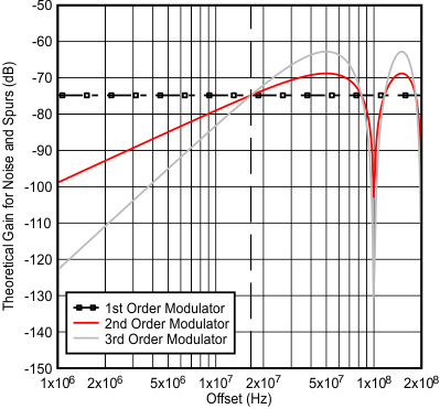
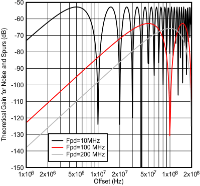
Figure 59 and Figure 60 give an idea of the theoretical impact of the delta sigma modulator order on the shaping of the phase noise and spurs. In terms of phase noise, this is what one would theoretically expect if strong dithering was used for a well-randomized fraction. Dithering can be set to different levels or even disabled and the noise can be eliminated. In terms of spurs, they can change based on fraction, but they will theoretically pushed out to higher phase detector frequencies. However, one must be aware that these are just THEORETICAL graphs and for offsets that are less than 5% of the phase detector frequency, other factors can impact the noise and spurs. In Figure 59, the curves all cross at 1/6th of the phase detector frequency and that this transfer function peaks at half of the phase detector frequency, which is assumed to be well outside the loop bandwidth. Figure 60 shows the impact of the phase detector frequency on the modulator noise.
 Figure 59. Theoretical Delta Sigma Noise Shaping for a 100 MHz Phase Detector Frequency
 Figure 60. Theoretical Delta Sigma Noise Shaping for 3rd Order Modulator