SNIA043A july 2021 – april 2023 TMP114 , TMP144
4.3 Under-Component Experimental Results
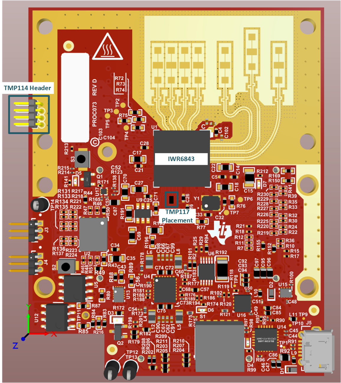
To further explore the topic of under-component temperature monitoring and test for accuracy and response time, a TMP114 temperature sensor was placed underneath the IWR6843 mmWave sensor on the IWR6843ISK evaluation board. The board layout files were modified to add the TMP114 temperature sensor footprint and then route the communication and power traces out to a header. This was to make sure that the operation of the radar board is not interrupted.
 Figure 4-6 IWR6843ISK Evaluation
Module
Figure 4-6 IWR6843ISK Evaluation
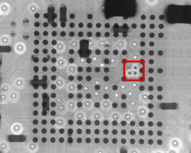
ModuleCorrect operation of the modified radar board was confirmed using the MMWAVE Out of Box Demo. An xray image was also used to collect more information about the placement of the TMP114 temperature sensor underneath the IWR6843 mmWave sensor.
 Figure 4-7 Xray Image of IWR6843 with TMP114
Temperature Sensor Underneath
Figure 4-7 Xray Image of IWR6843 with TMP114
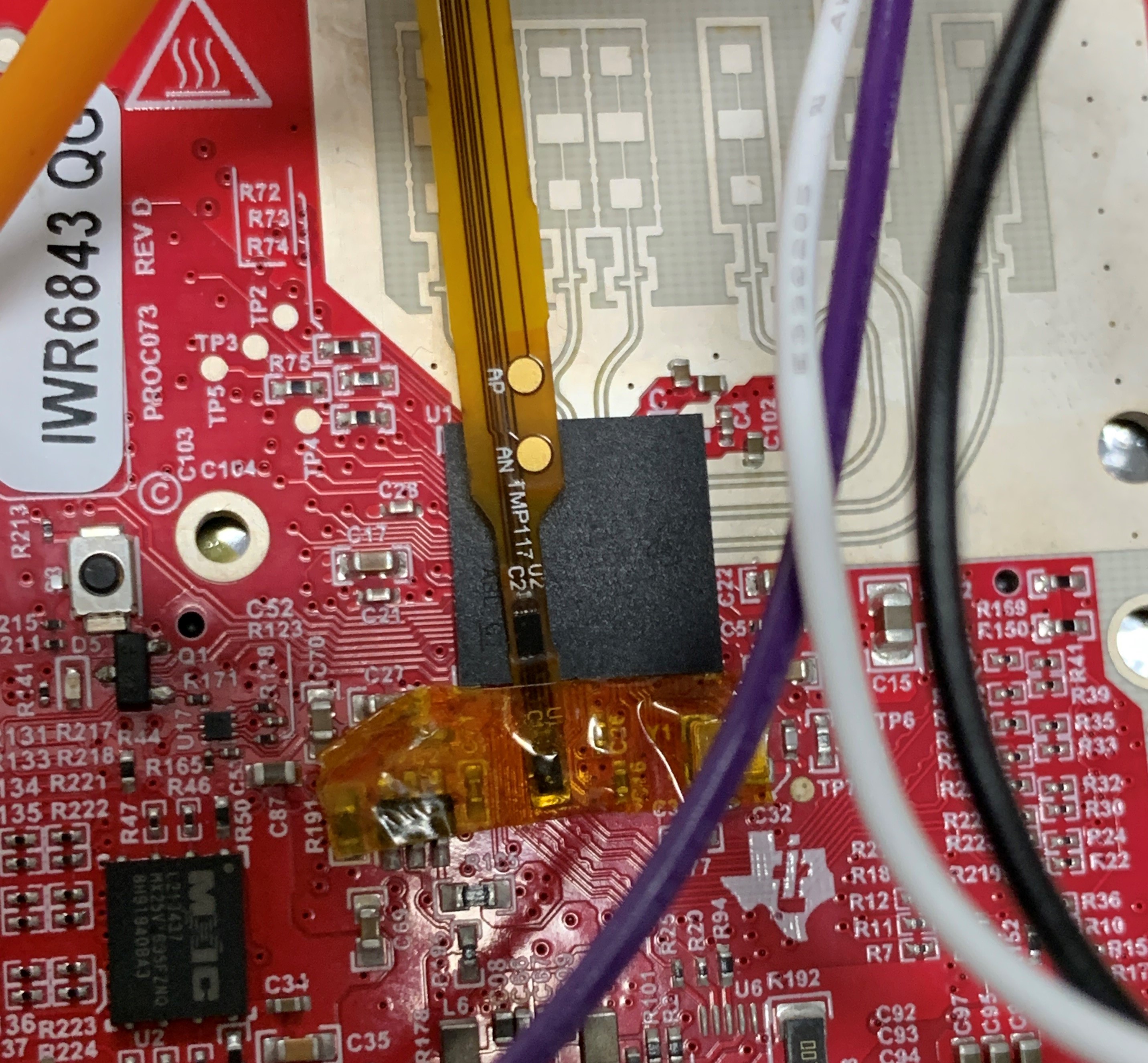
Temperature Sensor UnderneathTo compare the performance of the under-component TMP114 temperature sensor, a TMP117 temperature sensor was placed next to the radar processor. This was designed so that both sensors can be interfaced with an MSP430 microcontroller to read back temperature data in the same 500-ms interval.
 Figure 4-8 TMP114 and TMP117 Temperature
Sensor Testing Setup
Figure 4-8 TMP114 and TMP117 Temperature
Sensor Testing SetupThe temperature rise as the IWR6843 mmWave sensor begins heating up can be seen in Figure 4-9, which shows the difference in thermal response and accuracy between the two devices. On average, the TMP117 temperature sensor measures 3.6°C below the TMP114 temperature sensor as the processor temperature increases. Additionally, the TMP114 temperature sensor is able to respond to the temperature rise much more rapidly, and this increase in thermal response time shows the effectiveness of this type of sensor placement. Table 4-1 shows how quickly each device reached 30°C, as well as each measurement at the end of the test run. Especially in systems that rely on over- or undertemperature shutdown mechanisms, fast thermal response, and higher accuracy can keep systems running longer by avoiding unnecessary shutdowns.
| Temperature Sensor | Time to Reach 30 °C | Temperature After 152.9 Seconds |
|---|---|---|
|
TMP114 |
47.6 seconds |
37.2109°C |
|
TMP117 |
87.1 seconds |
33.2421°C |
 Figure 4-9 TMP114 and TMP117 Temperature
Comparison