SNLA335B september 2019 – may 2023 DS250DF210 , DS250DF230 , DS250DF410 , DS250DF810 , DS280BR810 , DS280BR820 , DS280DF810 , DS280MB810
- Optimal Implementation of 25G/28G Retimers versus Redrivers in Common Applications
- Trademarks
- 1Overview of TI 25G/28G Retimers and Redrivers
- 2When to use a Retimer Versus Redriver
- 3Retimers for Common Network Interfaces
- 4Link Training Support With TI Signal Conditioning Devices
- 5Retimer and Redrivers Part Selection
- 6Revision History
1 Overview of TI 25G/28G Retimers and Redrivers
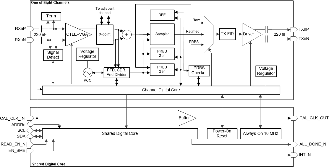
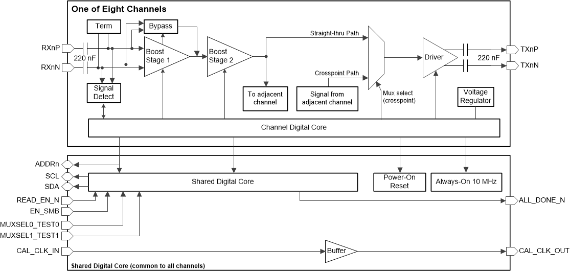
Figure 1-1 and Figure 1-2 illustrate the functional block diagrams for TI's 25G/28G retimers and redrivers. As evident from the block diagrams, the retimer and redriver have a few key functional differences.
- The retimer implements clock and data recovery (CDR) and sampler functional blocks, thus enabling it to output a retimed version of the input signal with lower jitter. The redriver on the other hand does not incorporate the retiming-CDR related functional blocks.
- The redriver implements a two-stage continuous time linear equalizer (CTLE) as its only form of receive equalization.
- In addition to CTLE, the retimer also implements a decision feedback equalizer (DFE). Thus the retimer is equipped with more enhanced post-cursor equalization function.
- The retimer incorporates additional diagnostic functions not available on the redriver, including PRBS pattern generation and checking and eye monitor functions.
 Figure 1-1 DS280DF810 Retimer Functional Block Diagram
 Figure 1-2 DS280MB810 Redriver Functional Block Diagram