SNLA420A September 2022 – January 2024 DP83TC812R-Q1 , DP83TG720S-Q1
3 Deterministic Real-Time Communication With Minimum Latency
Figure 3-1 shows latency and jitter affecting the real-time performance of a robotic system, which requires quantifying to make sure the necessary performance timings are possible.
 Figure 3-1 Key Points of Understanding
Determinism
Figure 3-1 Key Points of Understanding
DeterminismQuantifying jitter and latency performance define the maximum acceleration and speed at which the robot has controlled movements. Tests must be conducted on each physical layer (PHY) to determine the jitter and latency performance. The results of these tests provide understanding of the timing effects that a potential change of interface can have on system performance.
Therefore, the designer must be aware of the deadline requirement of the protocol, with this defined it can easily be determined if the chosen PHY can support the needed requirement by measuring the jitter and latency of this interface.
The quantification of determinism of the physical layer also influences the industrial protocol chosen. To date, no common industrial protocol has been finalized for use over a SPE PHY layer. Instead, designers have to either develop proprietary systems, or use protocols that have not been standardized, adding time and risk to development of a product. There are ongoing efforts to address this obstacle to adopting SPE in industrial environments, and there are already systems in the market using the technology.
To quantify and asses the deterministic performance of the Single Twisted Pair PHY, a test setup was built to perform these measurements. The test was built to emulate a daisy-chained industrial system, where test points were added to ease the measurements of the TX_CTRL and RX_CTRL MII signals. Figure 3-2 shows the system test setup.

Figure 3-2 System Test Setup for STE Latency Measurement
The host transmits and defines the Ethernet packet which is sent onto the cable. Subsystem 1 is built as a repeater function which forwards the packet to the next board. Subsystem N is built as a loop-back function which receives the Ethernet packet and transmits the packet back onto the same cable.
The modules are needed to emulate an industrial daisy-chained system which is typically used in industrial protocols like EtherCAT, Simple Open Real-Time Ethernet (SORTE), Profinet, and so forth.
Each of the modules has two Ethernet PHYs (PHY1 and PHY2) which add some latency to the transfer of the data packet. Figure 3-3 illustrates contributors of this latency.

Figure 3-3 Contributors of Latency in the Communication Layers
Figure 3-3 shows how these PHYs and the MAC contribute to latency. Each contributor is consecutively numbered from (i) to (iii). Figure 3-4 illustrates how to relate these numbered latencies back to the subsystems in Figure 3-2.

Figure 3-4 Latency Contributors in Each Subsystem
The latency contribution in Figure 3-4 is shown in one direction, for the measurement this means that for the host sending a data packet to subsystem 1, this packet is now in the MAC sent back from subsystem 1 to the host. This setup makes it possible to measure the cycle times of TI’s 100BASE-T1 and 1000BASE-T1 PHYs on a system level. In this case as previously stated, a 0.5m STP cable was used during testing.
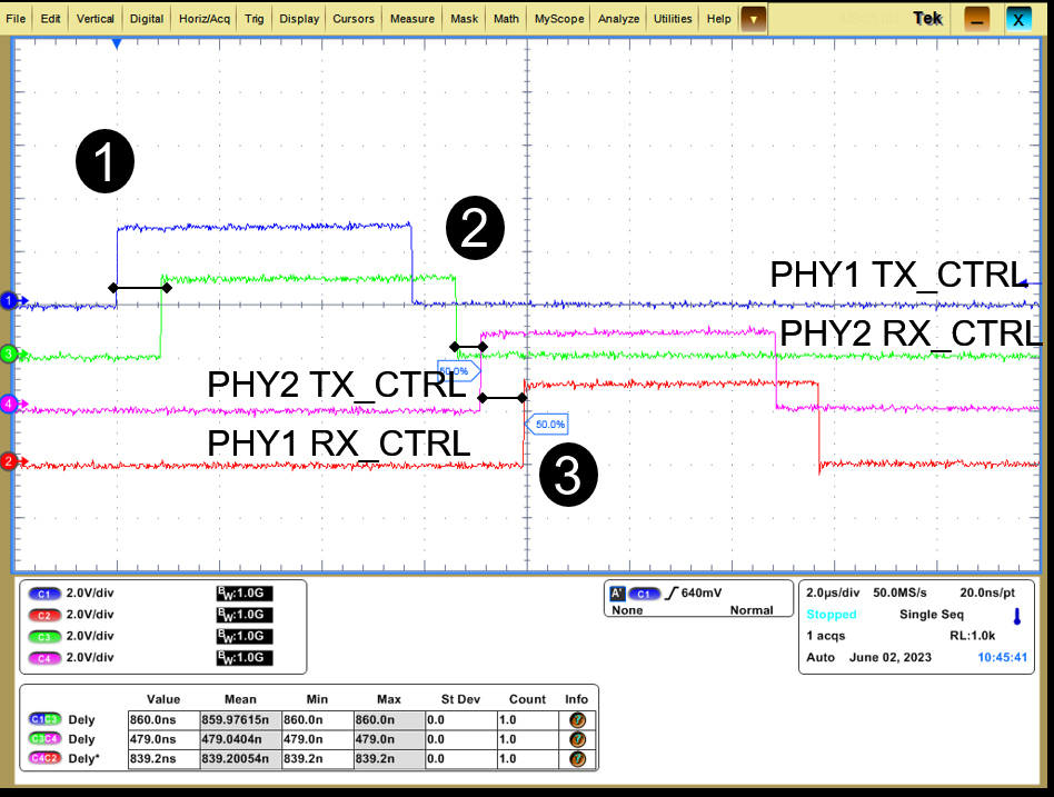
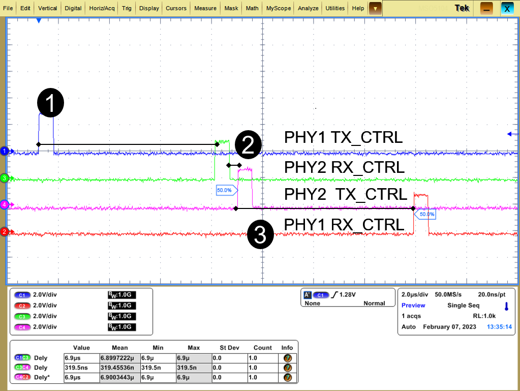
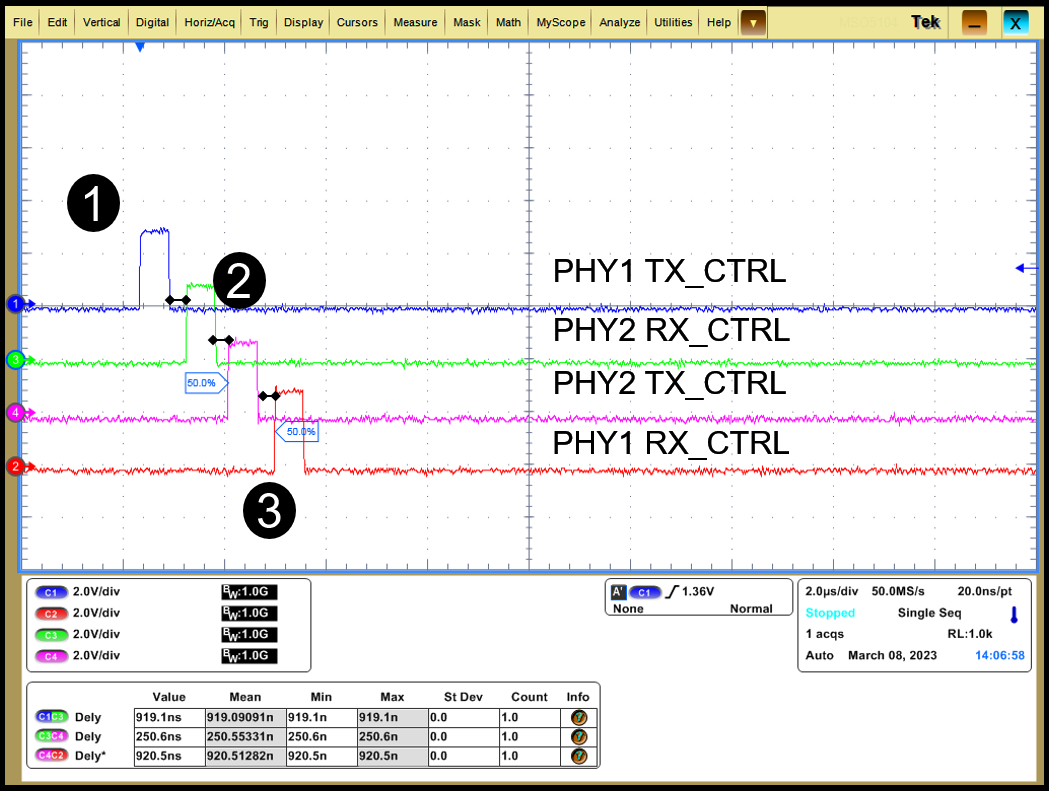
The following conditions apply for the screen grabs shown in Figure 3-5 through Figure 3-7.
- Measurement point 1 shows the total delay contribution of PHY1 (i) and PHY 2 (iii) showing the combined RX and TX latency of PHY.
- Measurement point 2 shows the delay contribution of MAC layer of the system.
- Measurement point 3 shows the total delay contribution of PHY2 (i) and PHY 1 (iii) showing the combined RX and TX latency of PHY.

Figure 3-5 DP83TC812 - 100BASE-T1 Cycle and Latency Timings

Figure 3-6 DP83TG720 - 1000BASE-T1 Cycle and Latency Timings, RS Encoder Block Enabled

Figure 3-7 DP83TG720 - 1000BASE-T1 Cycle and Latency Timings, PHY RS Encoder Block Disabled
Figure 3-5 shows the RGMII latency of the DP83TC812 PHY and the MAC latency of the AM64x Sitara™ processor. The PHY latency specification is also in the DP83TC812x-Q1 TC-10 Compliant 100BASE-T1 Automotive Ethernet PHY data sheet. Figure 3-6 similarly shows the RGMII latency of the DP83TG720 PHY and the MAC latency of the AM64x Sitara processor.
Cycle time is also affected by packet length, which is also needed to understand the bandwidth required on the chosen PHY layer. For the test setup, an Ethernet packet was defined the following way: 64 bytes of payload and 12 bytes of payload overhead. On top of the delay from system latency, the packet length time also needs to be considered. Table 3-1 lists the measured values from testing the system indicated in Figure 3-4.
By default, the DP83TG720 implements a Reed Solomon (RS) encoder for error control coding (ECC) and forward error correction (FEC). This encoding adds non-trivial latency to cycle time. For more information on Reed Solomon encoding, see the Reed Solomon Decoder: TMS320C64x Implementation application note.
| Ethernet Type | PHY Latency (1) (3) Transmit and Receive | MAC Latency (2) | Total Latency | Packet Length Time (76 Bytes) | Packet Length and Latency |
|---|---|---|---|---|---|
| RGMII – 100Base-T1 | 860ns | 480ns | 1340ns | 5666ns | 7006ns |
| RGMII – 1000Base-T1, RS FEC bypass mode disabled | 6900ns | 320ns | 7430ns | 566ns | 7996ns |
| RGMII – 1000Base-T1, RS FEC bypass mode enabled | 920ns | 250ns | 1450ns | 566ns | 2016ns |
What does this mean for system performance for a robot arm with 7 to 10 subsystems on a daisy-chain communication branch? The data in Table 3-2 is taken under the assumption that the packet is completely received before it is retransmitted. This comparison assumes that the full packet is sent as a half-duplex data transfer, even though the Base-T1 can support full duplex. Using the full duplex capability of the transceiver can improve the latency of the data transfer; however, using this feature of the PHY is heavily dependent upon the protocol used to implement the system.
The results in Table 3-2 indicate the time contributions from PHY latency, MAC latency, and packet length time
| Ethernet Type | Host | Subsystem 1 | Subsystem 2 | Subsystem 3 |
|---|---|---|---|---|
| RGMII – 100Base-T1 | 0 | 7.006μs | 14.012μs | 21.018μs |
| RGMII – 1000Base-T1, Encoder Enabled | 0 | 7.946μs | 15.892μs | 23.838μs |
| RGMII – 1000Base-T1, Encoder Disabled | 0 | 2.016μs | 4.032μs | 6.048μs |
| Subsystem 4 | Subsystem 5 | Subsystem 6 | Subsystem 7 | |
| RGMII – 100Base-T1 | 28.024μs | 35.030μs | 42.036μs | 49.042μs |
| RGMII – 1000Base-T1, Encoder Enabled | 31.784μs | 39.730μs | 47.676μs | 55.622μs |
| RGMII – 1000Base-T1, Encoder Disabled | 8.064μs | 10.08μs | 12.096μs | 14.112μs |
| Subsystem 8 | Subsystem 9 | Subsystem 10 | Full Loopback | |
| RGMII – 100Base-T1 | 56.048μs | 63.054μs | 70.060μs | 140.12μs |
| RGMII – 1000Base-T1, Encoder Enabled | 63.658μs | 71.514μs | 79.460μs | 158.92μs |
| RGMII – 1000Base-T1, Encoder Disabled | 16.128μs | 18.144μs | 20.16μs | 40.32μs |
This example only takes into account the time required to move the packet from the host to subsystem 10, the latency value is defined using MAC delay plus RX (PHY1) and TX (PHY2) latency to account for sending a packet through all subsystems and back to the host, the time is doubled, showed in the Full Loopback column in Table 3-2.
For this robot system, sending a packet back and forth can be performed every 40.32μs at the fastest, to 158.92μs at the slowest using 10 daisy-chained subsystems. These times limit the range of what is possible to achieve for a system-level defined maximum communication time.
For a robot using up to 10 subsystems, this time interval is typically fast enough to achieve good system performance.