SNLA464 July 2024 TUSB2E221
USB 2.0 is a well-known serial interface that is ubiquitous in personal, enterprise, and automotive electronics. USB 2.0 has changed very little since the creation in 2000, and supports a wide variety of applications operating at low-speed (LS), full-speed (FS), and high-speed (HS) data rates. USB 2.0's reliability and ease of implementation has made USB 2.0 one of the most popular interfaces in the world.
USB 2.0 also has the highest signaling levels with LS and FS amplitudes at 3.3V and utilizes more power than of all modern interfaces. This high voltage level can also cause technical challenges in some modern applications. A voltage of 3.3V can damage metal oxide in technology nodes where dielectric thickness is 7nm and below. In 2014, the USB Implementers Forum created the Embedded USB2 (eUSB2) Physical Layer Supplement to the USB Revision 2.0 Specification to address this process issue and increasing demand for power-efficient USB.
The eUSB2 interface enables USB communication using low-voltage 1.0V or 1.2V signaling, which avoids damaging sensitive digital components. The latest USB 2.0 designs today are adopting eUSB2 for the power-efficiency and process scalability benefits. The eUSB2 interface is expected to continue to proliferate as semiconductor technology continues to move towards smaller and smaller process. These are the top four things to know about eUSB2.
1. Easily Implemented in Existing USB 2.0 Designs
eUSB2 is a supplement to the USB 2.0 specification, which means it builds upon the already-existing USB 2.0 specification and shares many similarities. In a typical USB design, the USB 2.0 interface is implemented through multiple layers. In the case of a USB host, the USB protocol is implemented at the software level in the form of eXtensible Host Controller Interface (xHCI) compliant device drivers. Device drivers serve as a link between USB software and hardware, and most operating systems include USB drivers in any standard installation. Since eUSB2 is a physical-layer specification only, the changes are limited to hardware and operates using the same application software and drivers as USB 2.0.
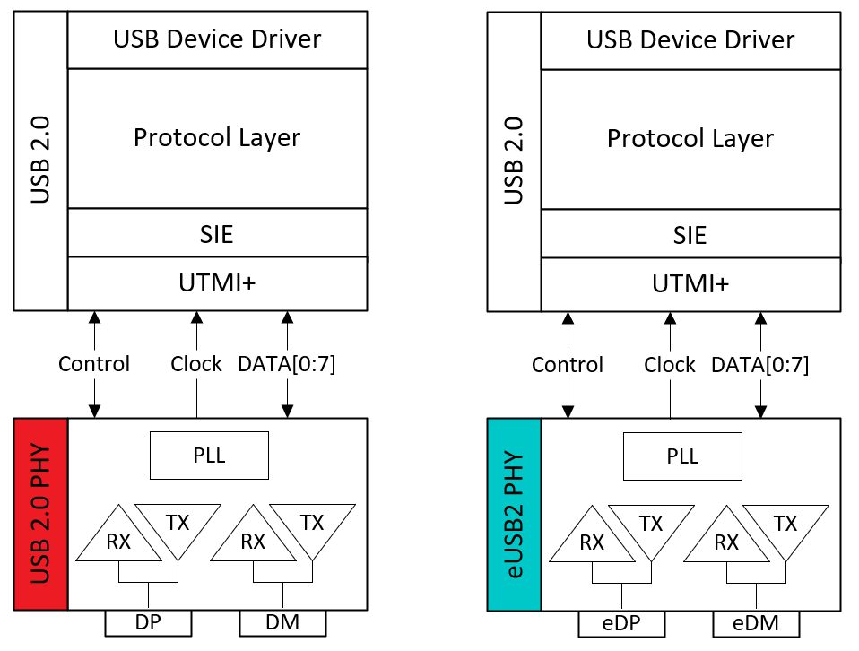
A Serial Interface Engine (SIE), whether implemented as part of the USB host or device, is the hardware interface between the parallel data specific to the design and the serialized USB data. The SIE can handle clock synchronization and communicates through the UTMI+ interface with a USB 2.0 PHY to produce signaling on D+ (DP) and D- (DM) as shown in Figure 1.
 Figure 1 USB 2.0 vs. eUSB2
The same SIE can be reused in an eUSB2 implementation; however, the USB 2.0 PHY can be replaced with a an eUSB2 PHY. The eUSB2 PHY can accept the control and data signals from the UTMI+ interface, and produce an output on eDP and eDM. This isolates the scope of the eUSB specification to the physical layer, and allows for ease-of-implementation in existing USB 2.0 designs. The same USB 2.0 software, device drivers, and much of the hardware can be reused, and little consideration is needed to implement eUSB2 in an existing design.
The primary difference between a USB 2.0 and eUSB2 design is the PHY. In comparison to a USB 2.0 PHY, the eUSB PHY transceiver operates on 1.2V or 1.0V instead of 3.3V. In additional to voltage differences, digital elements are used in a eUSB2 PHY to replace some of the analog mechanisms in a USB 2.0 PHY. For example, in traditional USB 2.0, a disconnect occurs when a SE0 is detected by the USB 2.0 host for longer than 2.5us. In eUSB this disconnect is detected by a digital ping, which is simplifies implementation.
The use of an eUSB2 PHY makes eUSB2 electrically incompatible with USB 2.0. Although there is a method to enable backwards-compatibility as discussed in Section 3, an eUSB2 device is not natively compatible with traditional USB 2.0 devices.
2. Electrically Incompatible With USB 2.0
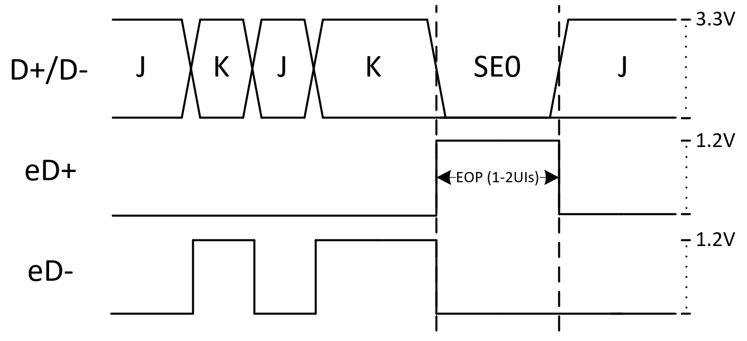
There is a common misconception that eUSB2 is simply USB 2.0 level-shifted from 3.3V to 1.2V. The signaling voltage in eUSB2 is reduced when compared to USB 2.0. LS and FS communication is reduced from 3.3V to either 1.2V or 1.0V as shown in Figure 2, and HS communication is reduced by about half from 400mV differential to 200mV.
The reduce signaling voltage provides power efficiency benefits and protects sensitive digital components. eUSB2 still supports the same standard data rates of LS (1.5Mbps), FS (12Mbps), and HS (480Mbps); however, LS and FS eUSB2 singling is also single-ended. In USB 2.0, LS and FS uses differential signaling; DP can be 3.3V and DM can be 0.0V during a "J" or idle state. In an eUSB2 FS application, both eDP and eDM can remain at 0V during a "J" state. USB 2.0 signaling is differential for LS, FS, and HS data rates, while eUSB2 is differential for HS data rates only. This change to single-ended LS and FS signaling in eUSB2 requires some common USB 2.0 patterns, like a single-ended 0 (SE0), to be modified
 Figure 2 FS USB vs. eUSB2 EOP
For example, Figure 2 shows a FS end-of-packet (EOP) pattern, which contains an SE0. For the initial J, K, J, and K states USB 2.0 uses differential signaling, where a "J" state is represented by DP being high and DM low. In the equivalent eUSB2 signal, the J and K state is dependent on the single-ended signaling on eDM.
As mentioned previously, the EOP starts with a SE0, which cannot be effectively represented in a eUSB2 single-ended signal. An alternative way to express the SE0 in eUSB2 is by pulsing eDP high for 1-2UIs. A simple voltage-shift from 3.3V to 1.2V cannot sufficiently convert between eUSB2 and USB 2.0 in this case and in many others.
High-speed signaling is differential in both eUSB2 and USB 2.0; however, there are still other physical-layer changes making them electrically incompatible. While USB 2.0 uses an envelope detector to determine USB 2.0 disconnect, eUSB2 uses an analog ping that is transmitted after every micro start-of-frame (µSOF). After not detecting an analog ping, the host can consider the eUSB2 device disconnected and issue a port reset with a single-ended 1 (SE1), an illegal line state in USB 2.0.
Some other notable changes being the transmit impedance for eUSB2 is 40Ω with a differential termination impedance of 80Ω, instead of the 45Ω and 90Ω impedances respectively required by USB 2.0. These make the process of converting between eUSB2 and USB 2.0 messages more complicated than a simple level-shifting operation.
Fortunately, the eUSB specification includes a method for backwards compatibility between eUSB2 and USB 2.0. In Section 3, we can discuss non-native eUSB2 modes that include an eUSB2 repeater.
3. eUSB2 Repeaters Enable Backwards Compatibility
As the name implies, eUSB2 was developed for embedded applications, where both the host and peripheral are eUSB2-compliant devices and located on the same PCB. In these cases, an eUSB2 link is said to be in native mode.
Native mode is primarily used for inter-chip interconnect in applications. Both the host and peripheral are connected directly through the eUSB2 interface as shown in Figure 3. eUSB2 is electrically incompatible with USB 2.0.

Figure 3 eUSB2 Native Mode
If support for a USB 2.0 host or peripheral is needed, a device called an eUSB2 repeater is utilized to enable backwards compatibility. An eUSB2 repeater converts between eUSB2 and USB signaling to enable communication between eUSB2 and USB 2.0 devices. An eUSB2 repeater is required to be configured as either a host repeater or peripheral repeater.
In applications where the eUSB2 device is a host and communication with a USB 2.0 peripheral is required, a eUSB2 repeater can be used in host mode to establish a connection. The eUSB2 host can send a configuration pattern through the eUSB2 interface to configure the repeater. Then, the eUSB2 host can communicate to the USB 2.0 device normally as shown in Figure 4.

Figure 4 eUSB2 Host Mode
An eUSB2 peripheral can also configure an eUSB2 repeater in peripheral mode to establish a connection between a traditional USB 2.0 host, and an eUSB2 device as shown in Figure 5.

Figure 5 eUSB2 Peripheral Mode
In addition to configuration, the eUSB2 supplement defines in-band signaling in the form of Control Messages (CM) to manage the repeater state machine. CMs can be used to transition the repeater into low-power states, put the repeater in test modes, and more. Control messages and their usage are defined in Table 1. With the notable exception of CM.RAP, CMs are not used in native mode. Register Access Protocol (RAP) can be used to access the vendor-defined register space of an eUSB2 repeater or peripheral directly through eUSB2. RAP is an optional feature introduced in eUSB2 to further simplify implementation.
| CM Name | Description | Usage |
|---|---|---|
| CM.FS | Revert to FS terminations | Repeater mode only |
| CM.L1 | Enter L1 Power State | Repeater mode only |
| CM.L2 | Enter L2 Power State | Repeater mode only |
| CM.Reset | USB 2.0 Bus Reset | Repeater mode only |
| CM.Test | Force enable HS terminations | Repeater mode only |
| CM.RAP | Start of register access protocol (RAP) access | Native mode, repeater mode |
The ability to dynamically configure and control an eUSB2 repeater as either a host or peripheral allows the repeater to also be used in dual-role applications, where the host and peripheral can swap roles. There is even possible to have two eUSB2 repeaters in a single link. When utilizing eUSB2 repeaters, eUSB2 has implications it has on the overall structure of the USB 2.0 tree.
4. USB 2.0 Compliance and Interop Considerations
A two-repeater application is used when both the host and device are eUSB2-capable, but require an eUSB2 repeater between the SoC and a USB 2.0 connector as shown in Figure 6.

Figure 6 Two eUSB2 Repeater Application
In the USB ecosystem, an eUSB2 repeater can be treated as a USB 2.0 hub tier, and each eUSB2 repeater in the link reduces the maximum number of allowable USB hubs by 1. Similarly to a hub, an eUSB repeater is allowed to consume up to 4 SYNC bits in an USB packet and extend the EOP width. Typically, 5 tires of USB hubs are allowed in the USB tree. In the two-repeater application, a maximum of 3 hub tiers are allowed. This is allowed according to eUSB2 specification, but if not properly accounted for it can cause interoperability and false compliance failures.
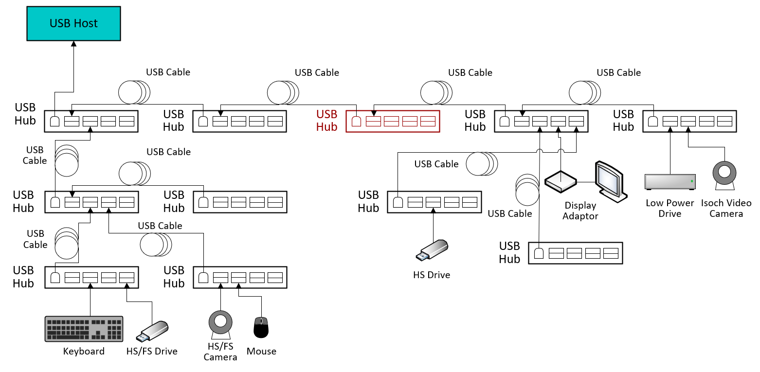
The standard USB interoperability test tree used for USB compliance testing shown in Figure 7 does not contain an eUSB2 repeater. The fist tier of USB hubs at the top of the diagram contains the maximum amount of 5 Hubs supported.

Figure 7 USB Host Interop Tree
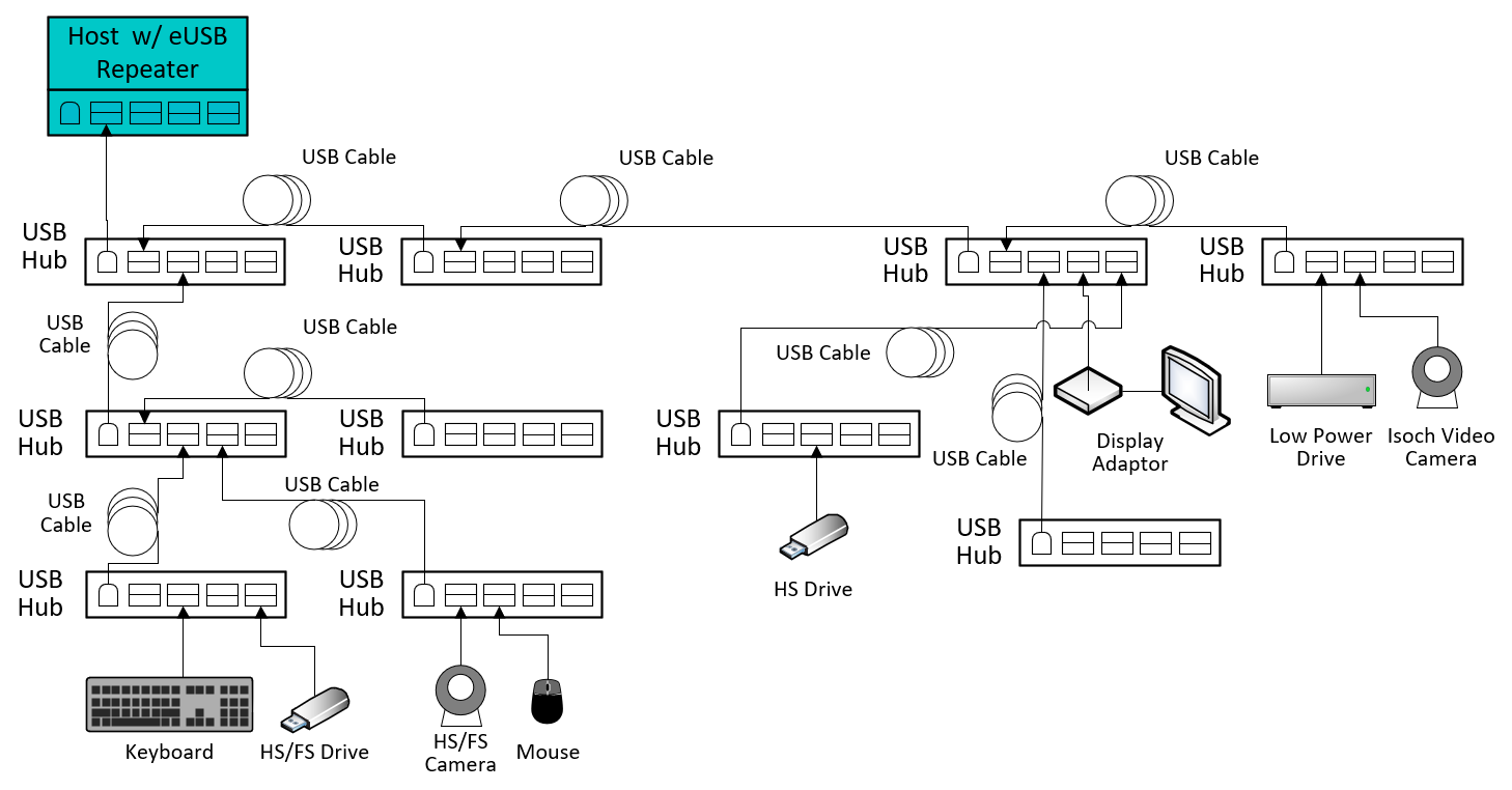
When adding an eUSB2 repeater, a hub must be removed to keep the tree USB compliant. In an application where an eUSB2 repeater is used in host mode, the number of maximum allowable hubs can be reduced by one, and the red hub can be removed. The modified interoperability tree shown in Figure 8, has a host that is utilizing an eUSB2 repeater with the tree is reduced by one hub tier. All the same device speeds, traffic, and cable links remain the same.

Figure 8 USB Host With Repeater Interop Tree
Likewise, when running USB 2.0 electrical compliance, an eUSB2 repeater can act similar to a hub with packets having allowable end-of-packet dribble and drop synchronization bits at the beginning of each packet. When performing USB 2.0 electrical compliance, this needs to be taken into consideration.
The eUSB2 interface enables the popular USB 2.0 interface to continue thriving as an essential part of USB applications. Although eUSB2 is still a relatively new interface, eUSB2 hosts, devices, and repeaters are only expected to grow as modern processors technology nodes continue to shrink below 7nm. The information in this document allows gives the most important insights into the eUSB2 specification and the applications.