SNLU245 February 2019 ONET1130EC
6 Typical Performance Results
A typical set of conditions for operating the EVM are as follows:
- VCC = 2.5 V, ICC = 300 mA with ROSA
- 10.71 Gbps, PRBS31 Pattern
- Transmitter Single-Ended Mode of Operation
- TOSA Temperature = 37°C
- Vea = –0.65 V
- Laser Bias Current = 0xF0 (approximately 53m A)
- Transmitter Modulation Current = 0xB0
- Transmitter Cross Point = 0xB0
- TX and RX CDRs Enabled
- Receiver amplitude set to 600mVpp
- Receiver de-emphasis set to 0x02
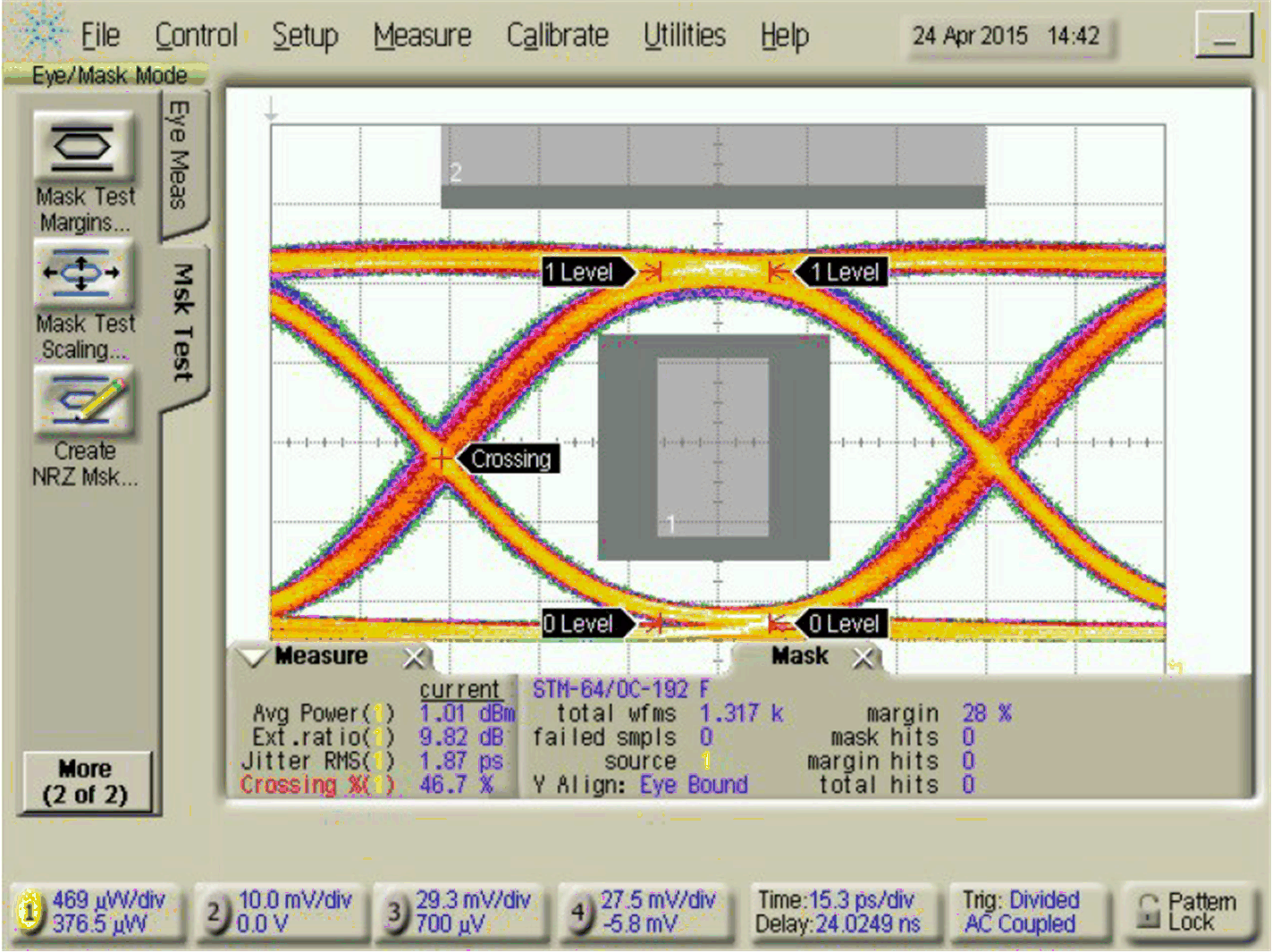
Figure 12 shows a typical unfiltered eye diagram.
 Figure 12. Unfiltered Transmitter Eye Diagram
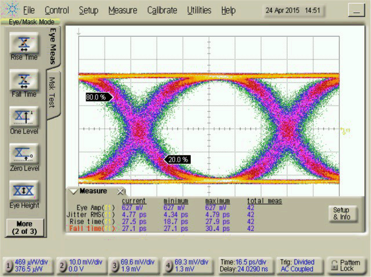
 Figure 13 shows a typical filtered eye diagram.
 Figure 13. Filtered Transmitter Eye Diagram
 Figure 14 shows a typical receiver eye diagram with the CDR enabled and -20dBm average optical input power to a PIN ROSA.
 Figure 14. Receiver Eye Diagram With CDR Enabled
 Figure 15 shows a typical receiver eye diagram with the CDR disabled and -20dBm average optical input power to a PIN ROSA.
 Figure 15. Receiver Eye Diagram With CDR Disabled