SNLU284 May 2020 LMH9135
3.2 S-Parameter Test Setup
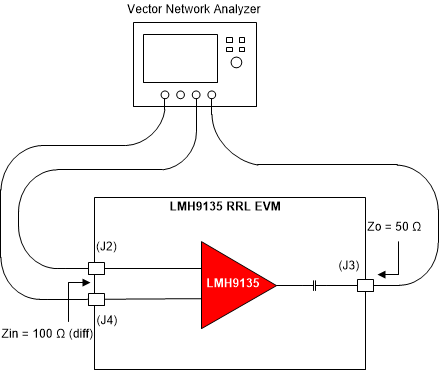
 Figure 3-2 S-Parameter Test Setup
Use the following guidelines for S-parameter measurement:
- S-parameter measurement is typically done using a Vector Network Analyzer (VNA), as Figure 3-2 shows. For measuring the LMH9135 EVM, a 4-port VNA is recommended which can generate and receive truly differential signals at the input and output ports.
- Before connecting the RF coax cables to the LMH9135 EVM, you must calibrate the VNA along with the cables using a calibration kit. This accounts for any cable losses in the S-parameter calculation at the VNA and helps set reference impedance at the cable ends.
- Make sure the frequency sweep and output power level from the VNA is set within the linear operating range of the LMH9135 devices. The resolution bandwidth (RBW) and dynamic range of the VNA can be adjusted to give optimum sweep time for the measurement.
- The trace plus connector loss for the board is about 0.35 dB for the input trace (differential) and 0.3 dB for the output trace in the middle of the frequency band. This may be accounted for improved accuracy in the measurements.