SNLU289 September   2020 DP83TG720R-Q1 , DP83TG720S-Q1


  1.   Trademarks
  2. 1Introduction
    1. 1.1 Overview
    2. 1.2 Hardware Features
    3. 1.3 Software Features
    4. 1.4 Block Diagram
  3. 2Board Overview
    1. 2.1 Components
    2. 2.2 Connectivity
      1. 2.2.1 Network Interfaces
      2. 2.2.2 USB Connection
      3. 2.2.3 Power Connection
  4. 3Quick Start
    1. 3.1 Jumper and DIP-Switch Settings
    2. 3.2 USB 2 MDIO Tool for Debugging and Configuration
  5. 4Configuration
    1. 4.1 Default Configuration
    2. 4.2 DIP-Switches and Operation Modes
    3. 4.3 DIP-Switch Settings Overview
  6. 5Update MSP430 Software Using UniFlash
  7. 6Schematic, Board Layout, and Bill of Materials
    1. 6.1 Schematic
    2. 6.2 Board Layout
    3. 6.3 Bill of Materials

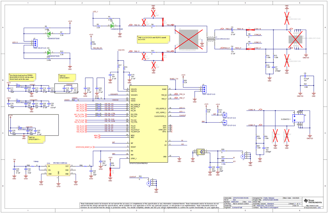
Schematic

GUID-20200914-CA0I-XV3G-VHBH-JNTBRT8MFN3R-low.gif Figure 6-1 Schematic : DP83TG720 Schematic

GUID-20200914-CA0I-XRTJ-1SXW-QFXZ07W3TRJW-low.gif Figure 6-2 Schematic : DP83867 Schematic

GUID-20200914-CA0I-S7MS-C8CG-2VZKGC3DGSKW-low.gif Figure 6-3 Schematic : MCU

GUID-20200914-CA0I-HR1P-HFPX-ZQR1S2VH9TT8-low.gif Figure 6-4 Schematic : Power