SNLU341A December 2023 – July 2024 MCT8314Z
2.1 Quick Start Guide
The MCT8314ZEVM requires a power supply source, which has a recommended operating range from 4.5V to 35 \V. To set up and power the EVM, follow the sequence below:
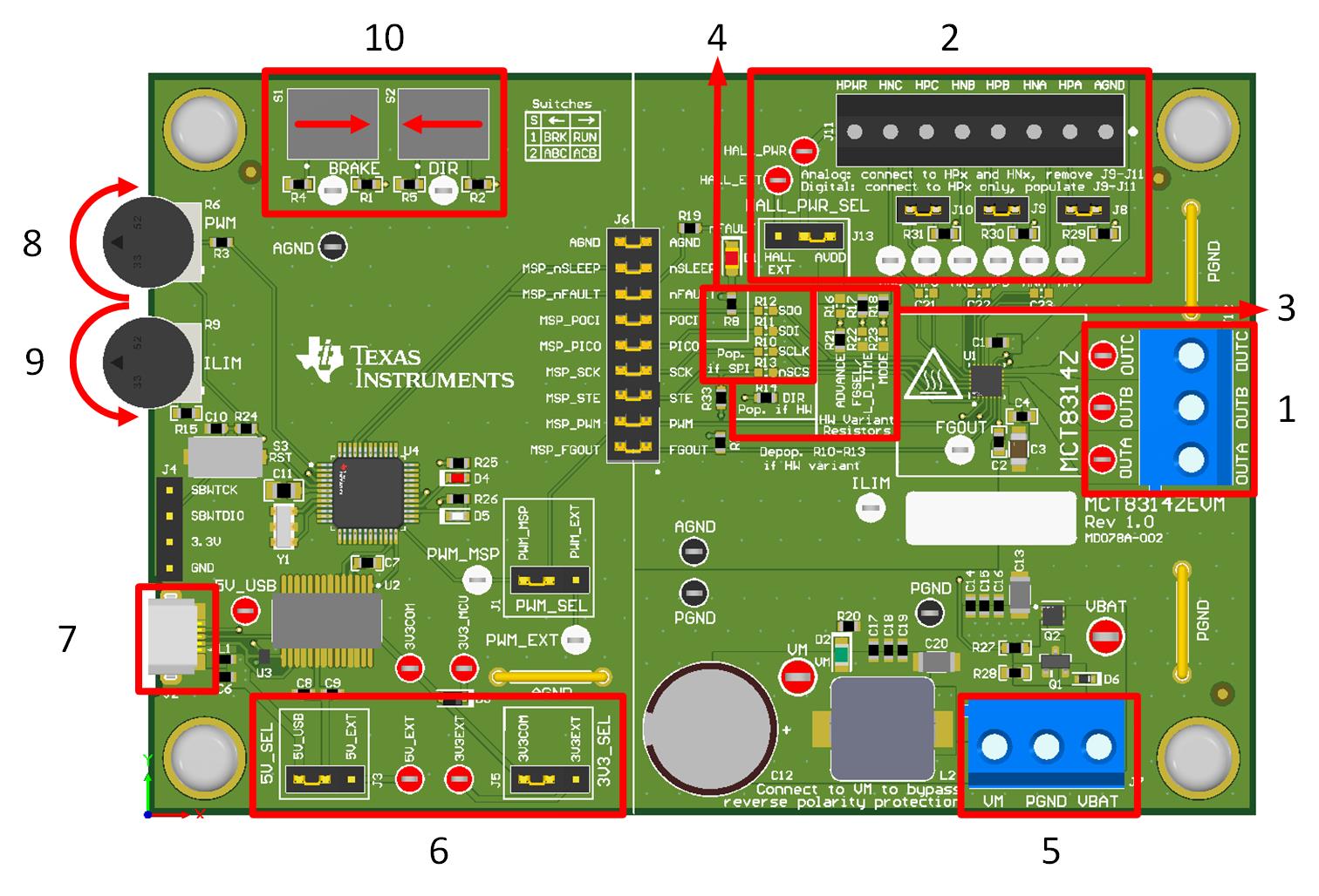
- Connect motor phases to A, B, and C on connector J12.
- Connect Hall sensors to J11 and select Hall power supply to come from AVDD or an external Hall supply using J13.
- If using digital Hall inputs, populate J8–J10 with shunt jumpers to enable pull-ups. Connect the single-ended inputs to only the HPx pins on connector J11.
- If using analog Hall inputs, remove J8-J10 and connect differential Hall inputs to HPx and HNx on connector J11.
- If using the MCT8314ZH, populate the Hardware (HW) variant resistors to set the desired device settings as described in Section 2.7.1.
- If using the MCT8314ZS, populate the SPI variant resistors.
- Do not turn on the power supply yet. Connect the motor supply to VBAT or VM and PGND on connector J7.
- To enable the reverse polarity protection and Pi filter, connect to VBAT. Note, that when connecting to VBAT, VM is VM – 0.7V less due to a diode drop in the reverse-polarity protection circuit.
- To disable the reverse-polarity protection and the Pi filter, connect to VM.
- Select J3 to 5V_USB and J5 to 3V3COM to power MSP430 from USB power supply.
- Connect the micro-USB cable into the computer.
- Turn the R6 potentiometer fully clockwise to set the motor to zero speed upon power up.
- Turn the R9 potentiometer fully counterclockwise to set the current limit to the max value.
- Flip the switch S1 to the right to configure BRAKE = RUN and switch S2 to the left to configure DIR = ABC.
- Turn on the motor power supply.
- Use the R6 potentiometer to control the speed of the motor, the R9 potentiometer to control the cycle-by-cycle current limit, and the switches to disable the motor driver, change the motor's direction, or brake the motor. Optionally, use the MCT8314Z GUI, refer to Section 3.1, to monitor the real-time speed of the motor, put the MCT8314Z into a low-power sleep mode, and read status of the EVMs LEDs.
Note:
If the EVM in use is labeled as MD078E1, then do not use the R9 or R6 potentiometers. To apply a speed signal, move jumper J1 to PWM_EXT and connect a PWM generator to the PWM_EXT test point. To set the cycle-by-cycle current limit, populate the R15 resistor with the desired value as described in Section 2.7.
 Figure 2-1 Reference for Quick Start Guide