SNOA961A February   2017  – February 2023 LDC2112 , LDC2114 , LDC3114 , LDC3114-Q1


  1.   Inductive Touch System Design Guide for HMI Button Applications
  2. 1Mechanical Design
    1. 1.1 Theory of Operation
    2. 1.2 Button Construction
    3. 1.3 Mechanical Deflection
    4. 1.4 Mechanical Factors that Affect Sensitivity
      1. 1.4.1 Target Material Selection
        1. 1.4.1.1 Material Stiffness
        2. 1.4.1.2 Material Conductivity
      2. 1.4.2 Button Geometry
      3. 1.4.3 Spacing Between Target and Sensor
    5. 1.5 Layer Stacks of Touch Buttons
      1. 1.5.1 Conductive Surface
      2. 1.5.2 Non-Conductive Surface
    6. 1.6 Sensor Mounting Reference
    7. 1.7 Sensor Mounting Techniques
      1. 1.7.1 Adhesive-Based
      2. 1.7.2 Spring-Based
      3. 1.7.3 Slot-Based
    8. 1.8 Mechanical Isolation
  3. 2Sensor Design
    1. 2.1 Overview
      1. 2.1.1 Sensor Electrical Parameters
      2. 2.1.2 Sensor Frequency
      3. 2.1.3 Sensor RP and RS
      4. 2.1.4 Sensor Inductance
      5. 2.1.5 Sensor Capacitance
      6. 2.1.6 Sensor Quality Factor
    2. 2.2 Inductive Touch
    3. 2.3 LDC211x/LDC3114 Design Boundary Conditions
    4. 2.4 Sensor Physical Construction
      1. 2.4.1 Sensor Physical Size
      2. 2.4.2 Sensor Capacitor Position
      3. 2.4.3 Shielding INn traces
      4. 2.4.4 Shielding Capacitance
      5. 2.4.5 CCOM Sizing
      6. 2.4.6 Multi-Layer Design
        1. 2.4.6.1 Sensor Parasitic Capacitance
      7. 2.4.7 Sensor Spacers
      8. 2.4.8 Sensor Stiffener
      9. 2.4.9 Racetrack Inductor Shape
    5. 2.5 Example Sensor
  4. 3Summary
  5. 4Revision History

Slot-Based

A third sensor integration technique is to insert the coil into a slot. Before inserting the sensor coil, memory foam pads are glued to both sides of the coil. This step can be integrated into the PCB fabrication process. When squeezed, the memory foam pads become thinner than the width of the slot and thus can be inserted easily. After the foam pads are inserted into the slot, they restore to fill the entire slot within a few seconds and serve as the “spacer” between the target and coil. The coil will be placed right in the middle of the slot. The unique sensor enclosure is a more rigid structure compared to that of the previous solutions. This approach provides the best immunity against undesirable mechanical interference such as twisting and pinching.
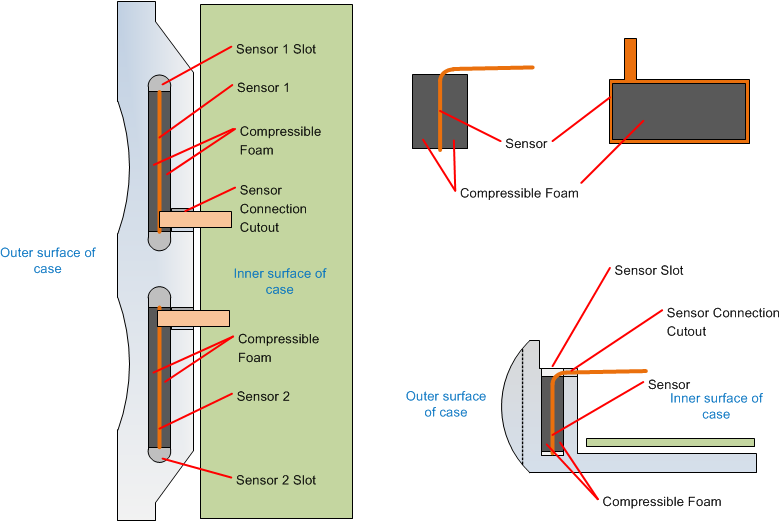
GUID-9C15886F-EC06-4621-AA6D-7D1B5E587D0B-low.pngFigure 1-12 Slot-Based Sensor Structure

Copper foil can be used to make a “Faraday Box” to completely shield the sensor in strong EMI environment, such as wireless charging.

GUID-412CAF6C-27F3-473F-BEA3-C3A5BB5CAA8B-low.pngFigure 1-13 Copper Foil Shielded “Faraday Box”