-
Inductive Touch – Configuring LDC2114 and LDC3114 Touch-Button Sensitivity
Inductive Touch – Configuring LDC2114 and LDC3114 Touch-Button Sensitivity
Trademarks
All trademarks are the property of their respective owners.
1 Inductive Touch Buttons – The Working Principles
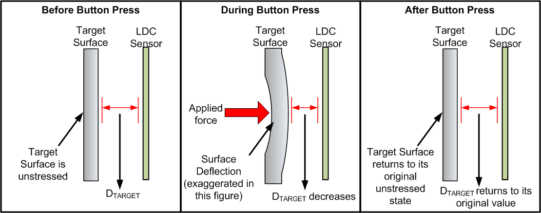
The three main components of the inductive touch button technology are the inductive sensor, target surface, and an inductance-to-digital converter. As shown in Figure 1-1 when a force is applied on the target surface, the material deflects slightly, reducing the distance between the inductive sensor and the target surface (DTARGET). This change in DTARGET changes the inductance of the sensor (Δ Sensor Inductance ∝ Δ DTARGET), which is measured by the inductance-to-digital converter. When the force is removed the surface returns to its original unstressed shape.
 Figure 1-1 Inductive Touch Components
The primary factors that contribute to the sensitivity(1)of an inductive touch button are:
1.1 Target Distance (DTARGET) and Sensor Size
Inductive sensing relies on the interaction of EM fields generated by the inductive sensor and the eddy currents(2) being induced on the conductive surface. The amount of eddy currents induced on the target surface decreases with an increase in DTARGET as the target conductive surface now captures a smaller portion of the electromagnetic field generated by the inductive sensor. In turn, the physical size of electromagnetic field lines generated by an inductive sensing coil is directly proportional to the diameter of the sensor. Figure 1-2 shows how to set DTARGET as a percentage of the coil diameter for inductive touch.
 Figure 1-2 Button Sensitivity as a Function of DTARGET
1.2 Target Material
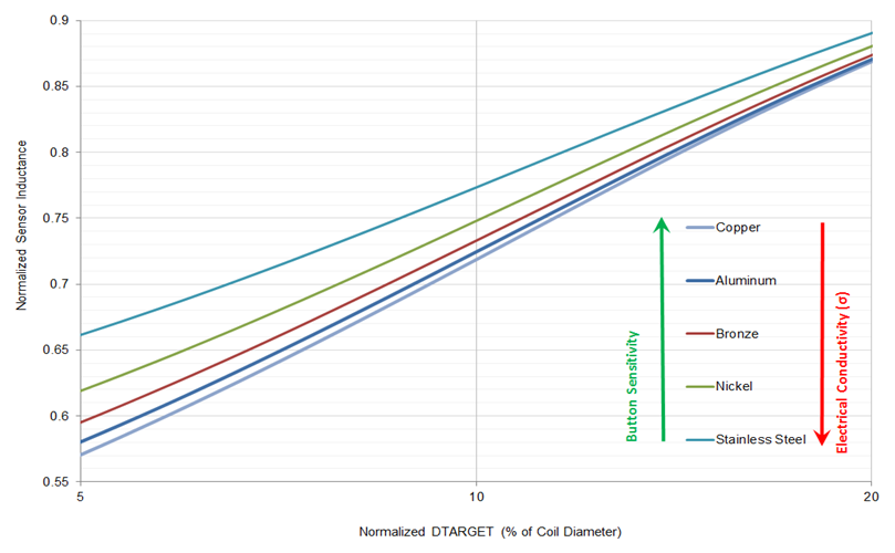
A material with higher electrical conductivity (σ) is a better target for inductive sensing technologies. The amount of eddy currents generated on the target surface are directly related to σ of the target material making higher conductivity materials such as copper or aluminum optimum targets for inductive touch buttons. Figure 1-3 shows the normalized inductance response plotted against DTARGET as a percentage of the coil diameter for different target materials. Copper and aluminum exhibit larger shifts in inductance with target movement resulting in a higher measurement resolution.
 Figure 1-3 Button Sensitivity as a function of the Electrical Conductivity of Target
Because inductive sensing works on the principle of eddy currents, which are a surface phenomenon, a very thin layer of a conductive material (for example, 0.08 mm of copper) can be added to non-conductive surfaces like plastic or glass to implement an inductive touch interface.
1.3 Target Thickness
Deflection produced in the target surface for a given amount of force is inversely proportional to Young’s modulus and thickness of the material. A given amount of force produces a larger deflection in a thinner or less stiff (lower Young’s modulus) material than a thicker or stiffer (higher Young’s modulus) one. Figure 1-4 shows how deflection decreases with respect to target thickness for different materials for a fixed button size.
 Figure 1-4 Deflection Decreases for More Rigid Materials
2 LDC211x and LDC3114 Gain Settings
Section 1 highlights that inductive touch button sensitivity can be affected by a few different factors. Some of these factors relate to the mechanical design and construction of the button enclosure and are sometimes complex to control or change in an existing design.
The LDC211x and LDC3114 devices address the need to control the sensitivity of inductive touch buttons through an easy-to-use register setting. Button sensitivity can be precisely tuned by adjusting the GAINn registers (0x0E, 0x10, 0x12, and 0x13) in these LDC devices.
The GAINn register field scales the normalized 12-bit DATAn output value. A higher GAINn value results in a higher DATAn value for a given amount of force applied to the target conductive surface. The 6-bit GAINn setting can be used to set the gain factor to values between 1 and 232. Each incremental GAINn value increases the gain factor by an average of 9% which provides enough granularity to precisely control the button sensitivity.
The GAINn setting does not affect the amount of deflection experienced by the button surface for a given amount of force nor does it affect the amount of inductance shift experienced by the inductive sensor.
Figure 2-1 shows how the button threshold can be configured to different amount of button activation force by simply tuning the GAINn register settings:
 Figure 2-1 Gain and Button Threshold
It is important to remember that the GAINn setting does not have a significant impact on the noise observed on the DATAn output. This is a result of the extremely low noise architecture of the LDC211x and LDC3114 devices. Figure 2-2 shows SNR for a given amount of force across a range of gain factors:
 Figure 2-2 SNR (dB) vs Gain Factor