SNOAA47A September 2024 – October 2024 TMP116 , TMP117 , TMP119
3.1 Hardware Setup
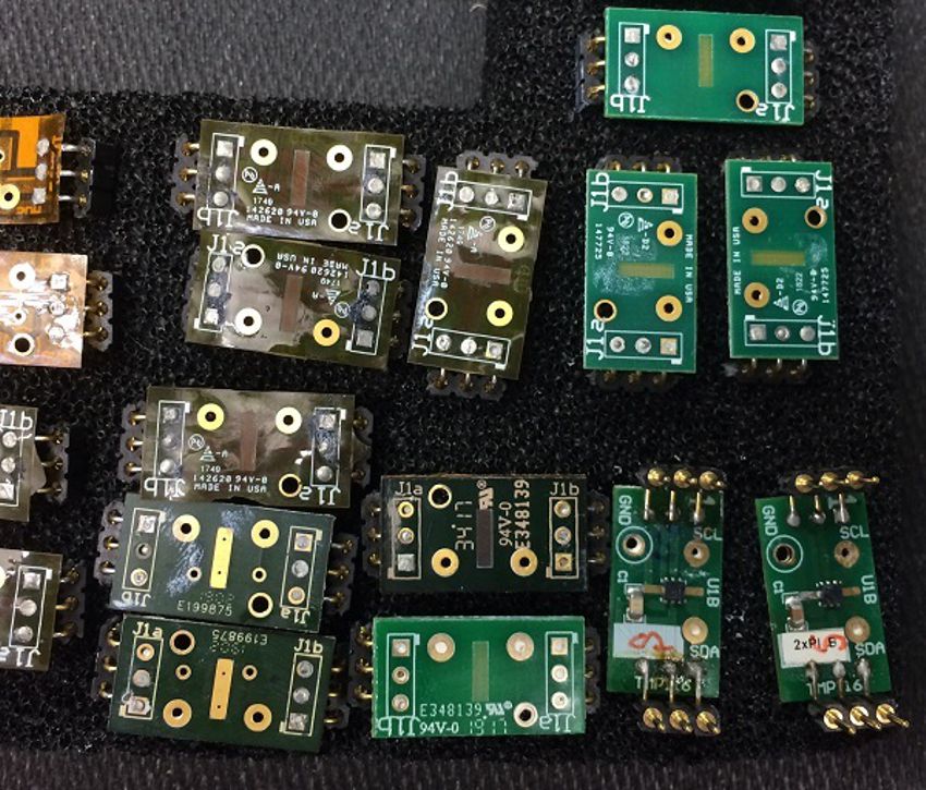
The purpose of the following measurements was to determine the thermal resistance values for the QFN and WCSP BGA packages of the TMP116, TMP117, and TMP119 soldered to PCB of varying thickness and composition.
The following parts and PCB were used during these tests:
- Devices
- TMP116 and TMP117 parts in the QFN-6 (DRV) package.
- TMP119/TMP117 parts in the WCSP-6 (YBG) package.
- Boards
- Rigid PCB (11mm × 22mm) coupon boards with a thickness of 64 mils.
- Rigid PCB (11mm × 22mm) coupon boards with a thickness of 32 mils.
- Flex PCB (11mm × 22mm) coupon boards with a thickness of 6 mil.
3–4 coupon boards (CB) were tested for each case. During the test runs, QFN packaged parts were assembled to examine both the soldered and non-soldered thermal pad (TP) conditions. DRV and YBG Parts Coupon Boards Used in the Tests shows various example coupon boards used in the tests.
 Figure 3-1 DRV and YBG Parts Coupon
Boards Used in the Tests