SNOU164B September 2018 – June 2024 TLV4021 , TLV4041
2.1.1 Usage Example
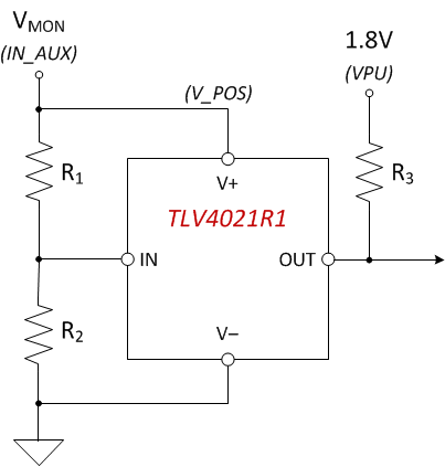
Figure 3-1 shows a typical use case of TLV4021R1 as an undervoltage monitor. Resistors R1 and R2 need to be installed on the EVM and the voltage to be monitored is applied to IN_AUX (DIP PIN 7). The configuration detects an undervoltage condition when the input voltage at IN_AUX drops below 2V. The output pull-up resistor R3 is connected to a 1.8V supply through VPU (DIP PIN2). The example assumes that the logic device that is connected to the output of the comparator operates at 1.8V.
 Figure 2-1 Usage Example
Listed below is the equation for deriving values for R1 and R2. For more details on this application, refer to the Applications section of the TLV40x1 Small-Size, Low-Power Comparator with Precision Reference data sheet.